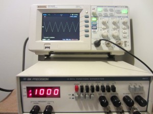
I got a used BK Precision 4011 5MHz function generator recently. The 4011 model is rather old and this particular unit was manufactured back in 1996. But BK precision still makes a similar model (4011A) which is identical to the older 4011 spec-wise except for the inclusion of an additional INV button for inverting the output waveform.

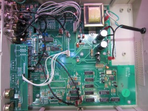
Since this is a rather basic function generator, I was not expecting to see too much inside. The following is a picture of the main circuit board and that is pretty much where everything is:

The majority of the circuitry is actually not for waveform generation. Everything below the center in the picture above is actually the support circuitry for the frequency counter, except perhaps for the MM5369 17 stage oscillator/divider, which is used as the external frequency reference for the main waveform generator chip.

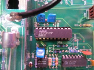
At the core of the 4011 function generator is a dedicated MM038CPP high frequency waveform generator chip (see picture above), which pretty much defines the capability of BK 4011. MM038 is capable of running at up to 20MHz, so presumably BK4011 can be hacked to run at much higher than rated 5MHz maximum frequencies (the frequency range of the output amplifier might be a limiting factor) with out too much efforts.
There are also a couple of additional PCBs towards the front of the unit which mainly handle the range switching and the display. The unit I got was a used one, so it may have been serviced before. If you take a look at the picture (BK4011_1) above, you can see that there is a capacitor soldered across the TTL/CMOS BNC connector. I am not entirely sure why that cap was added, but from the way it was soldered on I could only presume that it was added later after the unit was manufactured to compensate the output waveform.
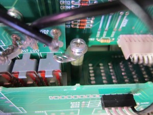
The grounding tab also looks interesting (see picture below), from the way it looks it doesn’t seem to have been used at all. But again, I don’t know whether it has always been like this or not.

While this function generator on its own does not have sweep capabilities, it can be easily added using the VCG input via an external sweep generator.
There are a few noticeable annoyances to this particular model. Since the waveform frequency is first measured and then displayed, it will take as long as 10 seconds for the displayed frequency to update at the lowest frequency range and it could take twice that long for the display to stabilize. Also, changing the frequency range will affect the actual set frequency output (for instance, if the current range is x500 and the set frequency is 100Hz, changing the range to x500K the frequency should read 100 KHz but the output will likely be off by a few percent).
Because the waveforms are generated by a dedicated chip and the displayed frequency is measured using the on-board frequency counter directly, BK 4011 will remain accurate as long as the main waveform generator chip is working. This function generator is also very easy to service and troubleshoot given the common logic chips it uses. So if you are looking for a cheap function generator, be certain to take a look at a used BK 4011.
Updates (12/23/2014)
Thanks Roger for providing the schematics for BK 4011 function generator. The schematics PDF can be downloaded here: 4011_schematic.pdf

