Last time I did a pretty thorough review of the X-TRONIC 4040 hot air rework/soldering station and shared my own experience with it. Overall, it is a very good entry level rework station. I have been using it intensely for the last week or so and it is holding up extremely well. Now let us take look at what is inside.
There is a seal on the back of the unit saying (in Chinese) that warranty would be voided if the seal is broken. But since the seal is just a thin piece of paper, I suspect that it may even break from the unit just being moved around during shipping and handling. In any event, taking the cover off is as simple as just removing eight screws, four on each side. There is not any mechanism to lock the cover in place so putting the cover back requires a little more effort since you have to match the screw holes exactly.
 |
 |
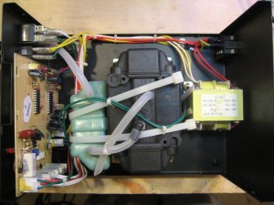
The first thing I noticed inside once I opened up the case is the Gordak brand marked on the pneumatic pump. Remember I wrote last time that I suspected that the unit was made by Gordak and was simply just re-branded as X-TRONIC? I even more positive this is the case now after seeing this. And if you look at the sticker on top of the transformer, you will also see “GD-952” printed on it. Presumably, this X-TRONIC 4040 is just a re-branded Gordak 952 model. In fact, I suspect that all those 952 hot air rework stations (e.g. KADA) are more or less originated from the same design and manufacturer.
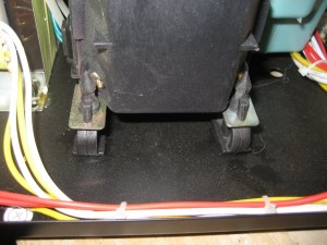
As you can see from the pictures above, the internal layout is fairly clean, and all wires are routed neatly. The pneumatic pump is mounted on top of a soft rubber frame to reduce the pump noise and vibration during operation. Also, the case is grounded at two places.
The pump itself is further secured by a few cable ties, and this is again a very typical assembling technique for devices at this price range.
The following YouTube video should give you an idea of what kind of environment this rework station might have been built in. Even though this video is for a different model (KADA 852D+), the actual construction should be more or less the same.
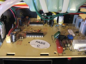
Now let us move onto the circuit board. Clearly, in order to reduce assembly cost, all the components used here are through-hole components and are all manually soldered. The PCB is single sided and its quality looks just so so, and the board does not seem to have any solder mask on the trace side.
Ideally, for this kind of circuit board we should really be using double-sided PCBs as there are components mounted on the other side of the board as well. But clearly, to keep the total manufacturing cost down every penny counts.
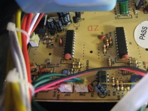
The two 20-pin ICs are presumably MCUs used to control the hot air, the soldering iron and to drive the two 7-segment displays. The circuitry around the two MCUs are virtually identical so clearly one chip is used for the hot air and the other one is used for the soldering iron. The manufacturer had sanded off the chip markings on the MCUs deliberately to make it harder for other competitors to copy the design.
 |
 |
There are three TRIACs (two BT136 and one BTA08-600C) used in the design, I assume that one is used for adjusting the pump speed and the other two are used for adjusting the hot air heater and the soldering temperature.
There are two random phase opt-isolators (MOC3023) used in conjunction with the two TRIACs to control the heating elements in the hot air wand and the soldering iron. Since the pump itself has no physical contact with anything else, its control circuitry does not have to be isolated. The hot air wand and especially the soldering iron has to be isolated since they come into contact with the components being worked on. The op-amps used for the temperature sensors are HA17358 dual operational amplifiers.
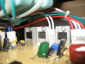
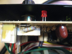
The soldering job quality is really just mediocre , which is more or less expected results from this kind of hand-soldering assembly line. As you can see that the components are not aesthetically aligned, and leads on some of the components soldered on the copper side of the PCB are not all properly trimmed. Look at the LED indicator in the picture below, did they simply just forget to trim the leads after soldering?
 |
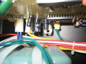 |
Also, there seems to be an improperly mounted TO-220 device (see picture to the right), it could be a transistor or a voltage regulator. But in general, TO-220 devices should be mounted on heatsinks which are then secured onto the PCB. But I guess this probably is not a big deal as the rework station is designed for stationary use only. But even so, the vibration from the pneumatic air pump could cause some stress on those soldering points.
Conclusions
Even though my review here for the internal construction is not all that rosy, considering the price of this rework station and its excellent performance I mentioned last time, it remains a good choice for engineers and hobbyist alike.

