I built a digital thermometer a couple of weeks ago. This thermometer uses an LM19 sensor calibrated for measuring a wide temperature range (-55 – 130 Celsius, -67 – 266 Fahrenheit) for outdoor temperature measurement and an SHT21 digital thermometer with humidity measurement for indoor use.
An ATmega328 microcontroller is used to read the temperatures from both an analog sensor LM19 using an analog input pin and a digital sensor SHT21 using the I2C bus.
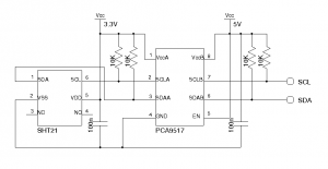
Since SHT21 uses 3V logic while the rest of the circuit uses 5V logic, a voltage translation circuit is necessary to interface SHT21 with the MCU. I used Taxes Instruments‘s PCA9517 level-translating I2C bus repeater as the voltage level shifter. The voltage shifting circuit is shown below:

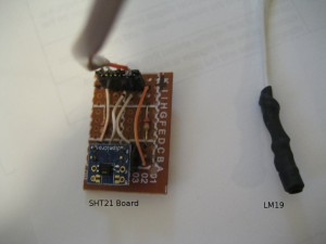
The SHT21 sensor is mounted on a breakout board and connected to the MCU board via a short cable. The LM19 sensor is encapsulated in a section of heat-shrinking tube and connected to the controller via a stereo cable. The cable length used can easily be extended to as long as 30 feet as long as the load capacitance is less than 300pF.

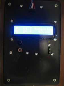
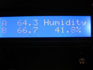
The following pictures show the temperature/humidity display in action:


The code used in this example can be downloaded here. Note that the constant 4.7 in the calculation of the temperature reading is a calibration value, which may differ from sensor to sensor.

