AD7705 and AD7706 are two 16-bit Sigma Delta ADCs. Equipped with on-chip digital filters and programmable gain front ends, these chips are ideal for low frequency multi-channel signal measurements. The main difference between AD7705 and AD7706 is that AD7705 has two fully differential input channels while AD7706 has three pseudo differential input channels.
This library I created interfaces with Arduino using the standard SPI bus. Most of the complexity is hidden behind the scene, and only a single parameter — the reference voltage — is needed to initialize the library since the reference voltage can vary depending on the particular implementation.
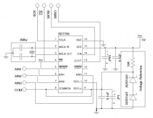
The following code snippet illustrates how to use this library. In this example, channel 1 of AD7706 is setup in bipolar mode with a unity gain. The common pin of the pseudo differential inputs (AIN1 to AIN3) is tied to the 2.5V voltage reference. This gives a measurement range of -2.5 V to +2.5 V. Pin SCK, CS, MOSI, MISO correspond to Arduino pin 13, 10, 11 and 12 respectively.
#include <AD770X.h>

//set reference voltage to 2.5 V
AD770X ad7706(2.5);
double v;

void setup()
{
 //initializes channel 1
  ad7706.init(AD770X::CHN_AIN1);

  Serial.begin(9600);
}

void loop()
{
  //read the converted results (in volts)
  v = ad7706.readADResult(AD770X::CHN_AIN1);
  Serial.println(v);
  delay(100);
}
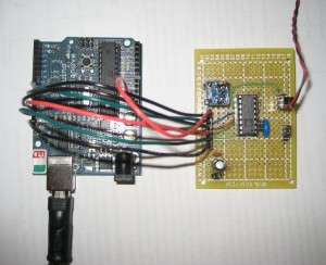
Here is the schematics I used for the sample program above:

For a supply voltage of 5V, the recommended voltage reference is AD780/REF192. I used two 1.25 V precision shunt voltage references ADR1581 to form a 2.5V reference instead since those are the components I have on hand.
The library also provides an overloaded init method to setup channel, gain and update rate:
void init(byte channel, byte gain, byte updRate);
The available gain settings are defined as:
  static const byte GAIN_1 = 0x0;
  static const byte GAIN_2 = 0x1;
  static const byte GAIN_4 = 0x2;
  static const byte GAIN_8 = 0x3;
  static const byte GAIN_16 = 0x4;
  static const byte GAIN_32 = 0x5;
  static const byte GAIN_64 = 0x6;
  static const byte GAIN_128 = 0x7;
And the update rate settings can be chosen from:
  static const byte UPDATE_RATE_20 = 0x0; // 20 Hz
  static const byte UPDATE_RATE_25 = 0x1; // 25 Hz
  static const byte UPDATE_RATE_100 = 0x2; // 100 Hz
  static const byte UPDATE_RATE_200 = 0x3; // 200 Hz
  static const byte UPDATE_RATE_50 = 0x4; // 50 Hz
  static const byte UPDATE_RATE_60 = 0x5; // 60 Hz
  static const byte UPDATE_RATE_250 = 0x6; // 250 Hz
  static const byte UPDATE_RATE_500 = 0x7; // 500 Hz
Other settings can be accessed via the setup register directly using the writeSetupRegister method defined below:
//Setup Register
//  7     6     5     4     3      2      1      0
//MD10) MD0(0) G2(0) G1(0) G0(0) B/U(0) BUF(0) FSYNC(1)
void AD770X::writeSetupRegister(byte operationMode, byte gain, byte unipolar, byte buffered, byte fsync)
For more details, please refer to the datasheet and the code in the download section.

Download AD770X.tar.gz (Obsolete)
4/18/2012: AD770X1.1.tar.gz (see this post for changes since the previous version)

