The tinySA Ultra is quite a capable spectrum analyzer. In this blog posting, we will take a look how to add a tracking generator to the tinySA with the help of an external mixer. I made a detailed video on this topic and be sure to check it out below.
Tracking generator is useful for determining the frequency response of filters. Without a tracking generator, the frequency sweep across the device under test (DUT) is independent of that of the spectrum analyzer. A common technique for capturing the frequency response using this method is to put the spectrum analyzer on maximum hold mode so that the result can accumulate over time. The main draw back obviously is the amount of time it would take to capture the complete characteristics. This method is usually fine when the filter is static, but it would not work if the filter response is time-varying.
And that is why filter response measurement is typically done with a spectrum analyzer in conjunction with a tracking generator. Here is some brief background: a tracking generator, as its name implies, tracks the frequency of the spectrum analyzer’s sweeping oscillator (typically this is the 1st LO of the spectrum analyzer) so that the tracking generator’s frequency output matches the center frequency of the bandpass filter in spectrum analyzer’s IF stage. Thus at any given moment, the spectrum analyzer sees the same frequency input as what it is currently sweeping at. The combination of a spectrum analyzer and a tracking generator is often referred to as a scalar network analyzer (SNA). Of course, a vector network analyzer (VNA) can also accomplish the same task.
The diagram below shows how you can build a tracking generator using the first LO output from a spectrum analyzer. I built a tracking generator for my HP 8566B spectrum analzyer a while ago using the same principle.
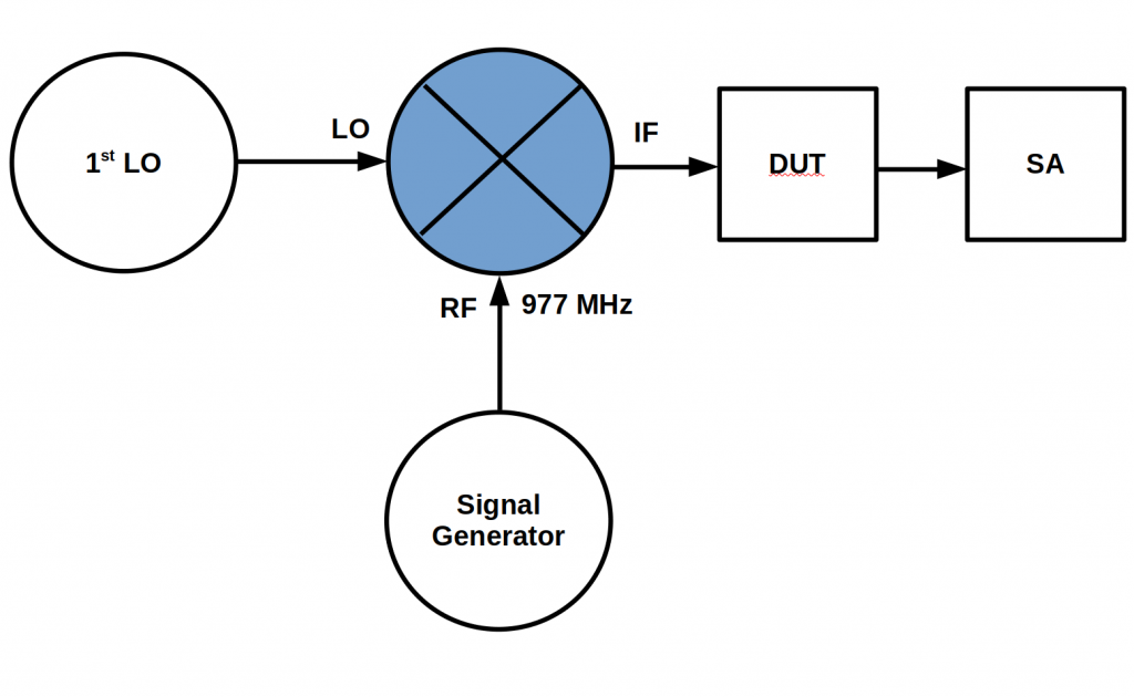
Here the RF frequency input into the mixer matches the center frequency of the IF filter and is subtracted from the LO, therefore the input frequency into the spectrum analyzer is in sync with SA’s sweep frequency at any given moment.
According to tinySA’s official documentation, the IF frequency should be centered around 980 MHz from the Si4468 transceiver chip. But I measured the LO frequencies over the entire zero-span frequency range of the tinySA (0 – 12GHz) and calculated the actual IF is between 977 MHz and 978 MHz, depending on the current center frequency on the tinySA. Because the IF filter’s bandwidth is narrow, it is important for the RF frequency input into the mixer to match the desired IF center frequency exactly as otherwise there will be significant roll-off in the frequency response.
Ideally, the RF input should be locked to the LO used in the SA. When this is not possible, the RF should be generated from a high stability source. In my experiments, I used my HP 8642B RF synthesizer for the 977 MHz signal.
While testing the LO output, I found a couple of interesting facts about the tinySA Ultra. First is that the LO level is at -10 dBm maximum, this is not ideal as most of passive double balanced mixers require a much higher LO level. While lower LO level would still work, it would incur significant conversion loss in the mixer, which further reduces the IF output level from the mixer. This translates into lower input signal level into the SA which reduces the dynamic range of the measurement.
The second fact is that there is a cut-over frequency for the LO. When the sweep frequency below 2.31 GHz for the tinySA, the LO sits at 977 MHz above the sweep frequency. For instance the LO is at 3.287 GHz when the sweep frequency is at 2.31 GHz. But once the sweep frequency goes above 2.31 GHz the LO folds under 977 MHz below the sweep frequency. Thus sweeping at 2.32 GHz, the LO changes to 1.342 GHz. This relation ship holds from 2.32 GHz all the way to the maximum zero-span frequency at 12 GHz. Of course at frequencies above 5 GHz, the LO level drops significantly. Because there is no LO leveling algorithm builtin, the response frequency will not be flat, this will affect the measurement accuracy especially over a larger frequency span. Also because the low pass filter was removed in “Ultra” mode, the frequency response will be poor over a wide bandwidth. So in reality, the useful tracking generator frequency range for the tinySA Ultra is limited to its non-Ultra mode, which is around 800 MHz.
So basically to add a tracking generator, all you need is an external mixer and a 977 MHz signal source. The picture blow shows the setup:
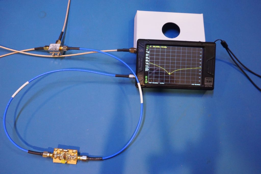
LO output is enabled on the tinySA Ultra and the LO signal is outputted from the CAL port. The LO is signal is connected to the LO port on the mixer as illustrated in the diagram before. The RF port on the mixer is connected to the 8642B RF signal generator which is outputting a 977 MHz 0 dBm signal. Finally the DUT is connected between the IF port of the mixer and the RF port of the tinySA Ultra.
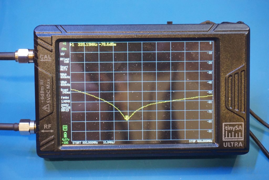
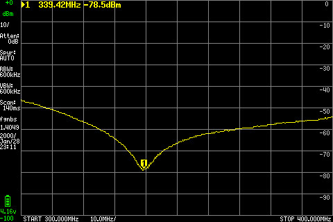
Here is a close-up of the trace and the captured image from the tinySA Ultra:
Here are a couple of pictures showing measuring the same filter with a liteVNA:
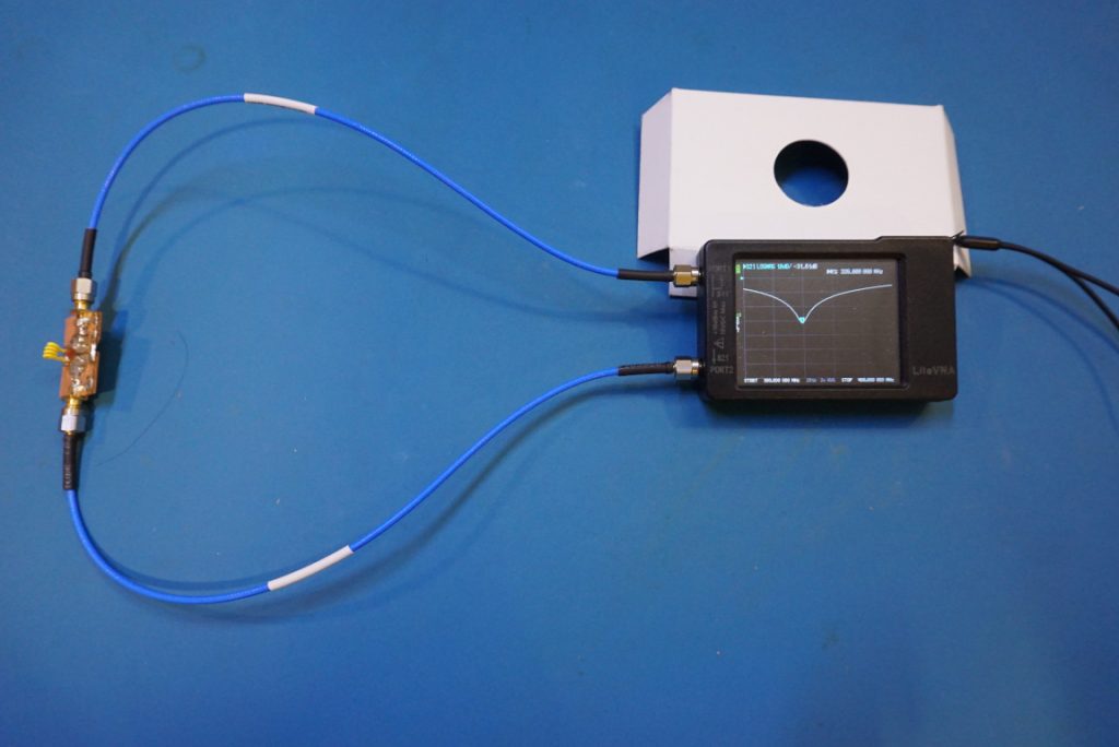
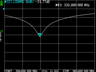
The mixer I used is the same one I used for the HP 8566B tracking generator, it is unfortunately not ideal in this case. Since the mixer is a Mini-Circuits’ ZX05-83-S+ 2300 MHz to 8000 MHz level 7 mixer, the RF frequency (933 MHz) is outside the operating frequency range of that mixer. Also as mentioned earlier, since the LO is at -10 dBm there is significant loss during the conversion. Due to these factors, the usable dynamic range is significantly reduced.
Combing through Mini-Circuits’ mixers catalog, it is actually pretty difficult to find a suitable passive mixer for this tinySA Ultra given the IF frequency and the LO power constraints. ADE-11X+, ZX05-43-S+, ZFM-4-S+ and SIM-43+ seem to be better suited as far as RF range is concerned but they are all level 7 mixers.
Because the IF frequency seem to change ever so slightly (between 977 MHz and 978 MHz) this also limits frequency span the tinySA Ultra can operate at any given time. Nevertheless, tracking generator is still useful for looking at a small frequency span, say a few hundred MHz.

