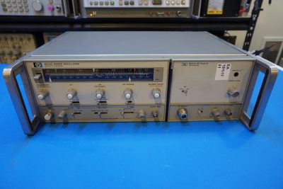
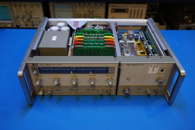
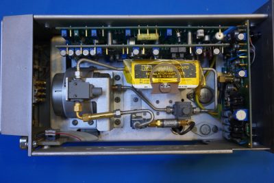
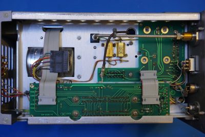
I just picked up an HP 8620C sweep oscillator with an HP 86245A 5.9 GHz to 12.4 GHz RF plugin on eBay. This time around though, the unit does not work. While it was advertised as a working unit I could not get it powered on and there was no sign of life whatsoever. So before I start troubleshooting and repairing the unit, I thought I would do a quick teardown to see what’s inside and if I could spot anything obvious that was out of the ordinary.
From what I understood, the HP 8620 series was first introduced in the early 1970’s (see here) and the “C” version was introduced shortly after. By the general appearance of the unit I received however, it appeared that my unit was manufactured at a much later date. And as you can see from the datecodes on various components in the later teardown pictures, this unit was built no earlier than 1988. It is quite impressive to see the life of a product line spanning two decades.
Similar to a lot of the HP test equipment in the same era that I had done teardown with (for example, the HP 8671A, HP 5350B and HP 436A), plugin boards are used extensively inside the HP 8620C.
By itself, the 8620C doesn’t do much. It is merely just a sweep control unit. To make it an RF sweep generator, you will need to have an RF module plugged in. According to the manual, there are at least a couple dozens of plugins available for the 8620C covering a frequency range from near DC to all the way up to 18 GHz.
The RF plugin in the unit I received is an HP 86245A which covers the upper C band, the entire X band and the lower end of the Ku band.
The first plugin board (brown) is the A1 sweep generator board. Like many HP equipment back in the days, most of the components have HP part numbers on them. The chip marked 1821-0001 for instance, is a CA3046 transistor array and the eight pin ceramic IC (marked 1826-0785) is an MC34002 JFET input OpAmp. The datecodes suggest that these components were manufactured in 1987 and 1988 respectively.
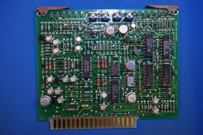
Next up is the A2 frequency control board (red). Look at the all the trim pots and OpAmps! Given the analog nature, these potentiometers must have been meticulously adjusted to ensure the accurate readings. There are also quite a few relays for switching in parts of the circuit for controlling different ramp schemes.
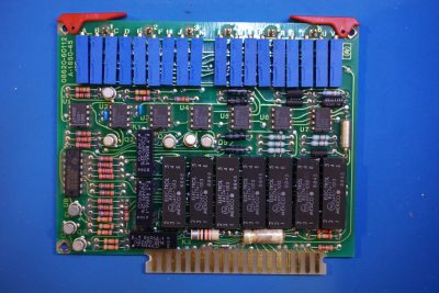
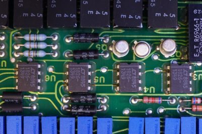
Here is a closeup of the OpAmps used on the frequency control board (HP part number 1826-1349), they are OP-02 general purpose operational amplifiers.
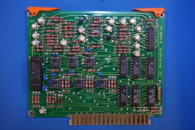
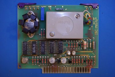
The next plugin board (orange) is the A3 logic assembly board. As the name suggests, it handles various logic including the startup control and marker trigger generator.
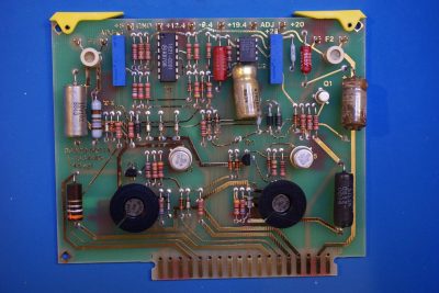
Here is the first visual clue that something was wrong with the sweep generator unit, this is at least part of the reason why the generator was not working. What you are looking at below is the A4 +20V and +5V regulator assembly board and two of the capacitors are clearly damaged. The electrolyte leakage was pretty severe and at least one terminal of each of the caps had rotten away.
[adsense]
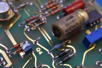
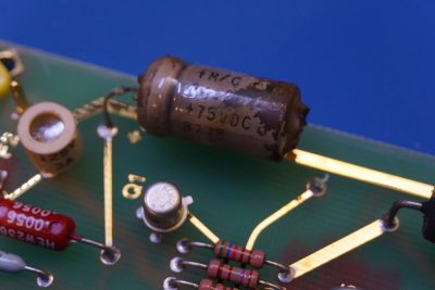
Here is a closeup of one of the failed capacitors. It is interesting to see that at least one capacitor on the same board appeared to be just doing fine.
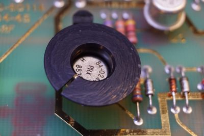
And here is a closeup shot of a transistor on heatsink on the regulator board.
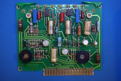
Now moving on to the A5 -10V and -40V regulator board. Again you can see one of the capacitors failed while the other three appeared to remain intact.
Here is a picture of that failed capacitor on the A5 board. These failed capacitors reminded me of the capacitor plague that dogged PC manufacturers back in the lat 90’s.
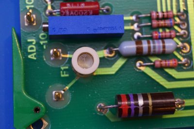
Both power supply board use SCR crowbars for over-voltage protection and in the event the output voltage swings beyond the predefined value and over-voltage is detected the SCR would be triggered and thus shorting out the supply rail so that the connected circuitry is protected. Shorting the output would in turn cause the input fuse to open and the corresponding power rail would be switched off until it is repaired. Here is a closeup picture of the fuse used on one of the power rails. The fuses can be easily checked via the corresponding test points on the circuit board.
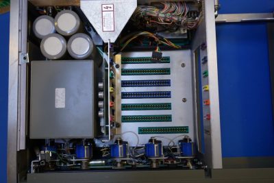
One slot is empty on the main board, and it is reserved for the A6 BCD programming assembly board (Option 001). Since the unit I have does not have that option, the slot remains unoccupied.
The last plugin card is the A7 operations control board which includes the fan PWM controller.
[adsense]
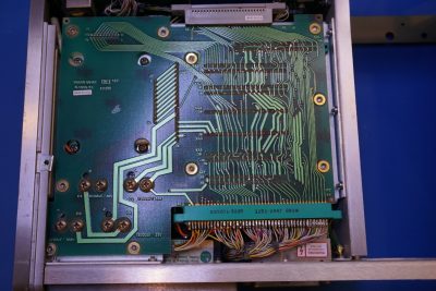
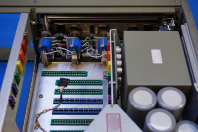
And the picture below shows the backplane where all the daughter boards plug into.
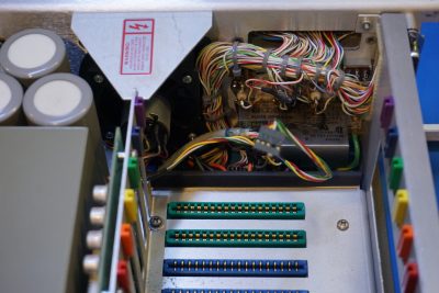
with the plugin boards removed, you can catch a glimpse of the front panel board and the power entry module located on the rear panel.
|
|
From a serviceability standpoint, the HP 8620C is not the easiest to repair as besides these easily removed plugin assembly boards, it would take quite some effort to remove the motherboard, the front and the rear panels if any of these areas need to be serviced. Look at the shear volume of the wiring!
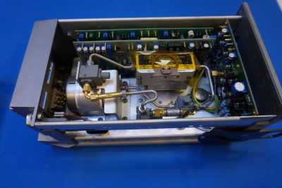
Finally here are a few pictures of the HP 86245A RF plugin. At the heart of this 4.9 GHz to 12.4 GHz RF generator is an YIG tuned oscillator. I did a detailed teardown of an YIG oscillator a while back while fixing my Wavetek 907 microwave frequency generator.
As you can see from the pictures below, the output signal from the YIG tuned oscillator goes through an amplifier (GaAs FET power amplifier) and then goes to the output. A small portion of the output signal is routed to the automatic level control (ALC) circuitry for adjusting the output power.
Here is a picture showing the underside of the 86245A. You can see the ridged coax connecting the output port of the RF directional coupler to the output N connector.
Finally, here is a video of the teardown. When I get a chance I will try to fix the 8620C and hopefully I can get it working again.
