DS3232 is an extremely accurate RTC with a guaranteed accuracy of 2.5 ppm (0 °C to 40 °C), which translates into an error of just 80 seconds over the course of a year under the worst case scenario. I had done a few projects using this chip before (you can read about them here).
While by default DS3232 is already very accurate, we can push its accuracy even higher by adjusting its aging offset register (8bit). This adjustment works by adding or subtracting the corresponding capacitance to or from the oscillator capacitor array. The adjustable range is represented as 2’s complement (-128 to 127) and each LSB change corresponds to roughly 0.1 ppm of change in frequency. So the overall adjustment range can be achieved programmatically is roughly ±13 ppm.
In its default configuration, the TCXO frequency is adjusted every 64 seconds depending on the environmental temperature by switching in or switching out capacitance via an internal look-up table. By utilizing the aging register, we can further null out any remaining offset. The aging offset adjustment is independent of the automatic adjustment via temperature compensation.
The code snippet below shows how to adjust the aging register of DS3232 via I2C. The full Arduino code listing can be found towards the end of the post. The aging offset register is at 0x10 and the valid values for the input parameter offset ranges from -128 to 127. Note that this number is later converted into 2’s complement before sending to DS3232.
void setAgingOffset(int offset)
{
    if (offset < 0) offset += 256;

    Wire.beginTransmission(DS3232_I2C_ADDRESS);
    Wire.write(0x10);
    Wire.write(offset);
    Wire.endTransmission();
}
Since normally the TCXO is adjusted every 64 seconds, in order for the changes to take effect immediately, we need to force the CONV bit (bit 5) to high in the control register (0x0E):
void forceConversion()
{
    Wire.beginTransmission(DS3232_I2C_ADDRESS);
    Wire.write(0x0E);

    Wire.write(B00111100);
    Wire.endTransmission();
}
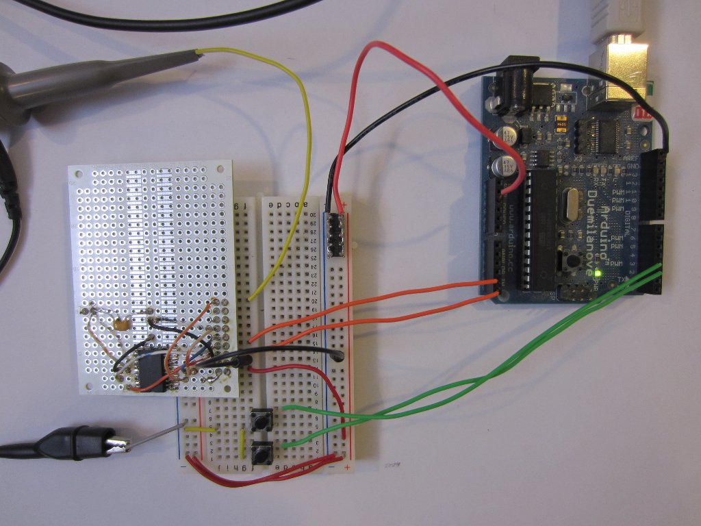
The picture blow shows my circuit setup. The DS3232 is soldered onto a protoboard using the reference design. The backup battery (CR2302) is on the other side of the board. Two buttons are attached to digital pin 2 and 3 for increasing and decreasing the offset value of the aging register. By default, the offset value is 0 and it can be adjusted between -128 to 127. If you have the Arduino serial monitor open while running the code, you can see the read back of the current aging offset value displayed.
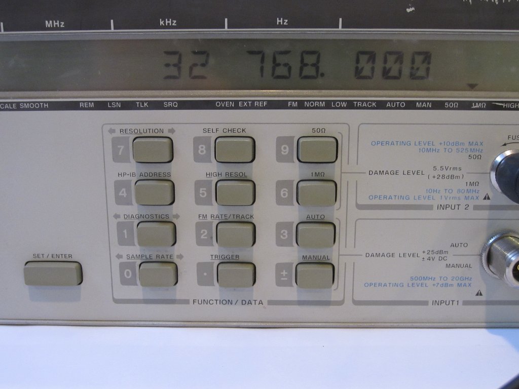
As mentioned earlier, each adjustment step changes the clock frequency by roughly 0.1ppm (which translates into roughly between 0.002 to 0.003 Hz). Here’s a picture showing the calibrated clock frequency and in this case the aging offset is adjusted to -40. The frequency is measured on my fixed-up HP 5350B in high resolution mode.
Finally, here’s a short video showing the adjustment process. Once the offset has been adjusted, power to the MCU can be disconnected and the value will remain as long as the chip is powered by the backup battery.
|
View on YouTube in a new window |


