Differential amplifiers come in handy in applications where common-mode noise and interference are present in the system. This is largely attributed to the very high common-mode rejection ratio (CMRR) these amplifiers provide. And because of the high CMMR they are well suited in high-side current measurement applications and in situations where voltages must be measured deferentially. So over the past couple of weeks, I made a differential amplifier PCB based on TI’s INA117 and it will serve as building blocks for some of my future projects.
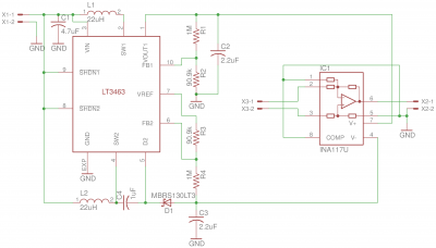
The schematic of this differential amplifier is shown below. Most of the circuitry is centered around an LT3463 DC/DC converter chip that is used to create the ±15V rails for the differential amplifier. The supply voltage to the LT3463 is very flexible and can be powered between 2.4V to 15V. So the entire circuit can be conveniently powered by two alkaline batteries or a single lithium cell.
The differential amplifier used here is a unit-gain INA117 which has a very high common-mode input range, up to ±200V. Since this design was meant to serve as a building block for other circuits, no impedance matching resistors are incorporated on the input side and no additional signal amplification is provided. Although the offset voltage and CMRR can be trimmed by adding external resistor networks between pin 1 and pin 5, by default the amplifier is accurate enough for most of the applications I have in mind. So to keep things simple. I tied pin 1 and pin 5 directly to the ground. According to datasheet, the typical offset voltage without any adjustment is only at around 0.1mV.
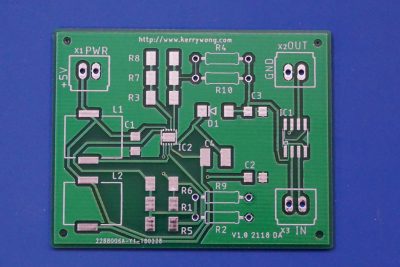
Here is the PCB I designed for this differential amplifier. Note that I substituted the resistor footprints with multiple paralleled resistors and used both through-hole and SMD footprints. This is based on the availability of the components I have on hand.
One thing worth noting is that the CMRR specified in the datasheet assumes using a low impedance source (<20Ω). Thus when the source impedance is higher the CMRR will drop accordingly and the gain error will manifest in the output. Typically, a compensation resistor with the same resistance of the source should be used. Please refer to the datasheet for more information.
In the video below, I showed how to use an SMD stencil to do reflow soldering using a hotair gun. The LT3463 DC/DC converter chip comes in a tiny 3mm/3mm DFN packaging with a lead pitch of only 0.5mm. Reflow soldering is pretty much the only option for handling this kind of chips.
And here is another video showing me doing a couple of measurements using the assembled boards.


