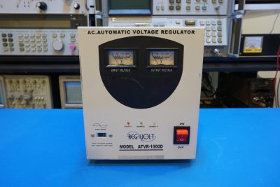
I bought a used RegVolt ATVR-1000D automatic AC voltage regulator (the model I got has long been discontinued, but you can find a current production model here) off eBay last week. This regulator was produced for the 110V market, but I suspect that with some adjustments I could get it to output 120V instead.
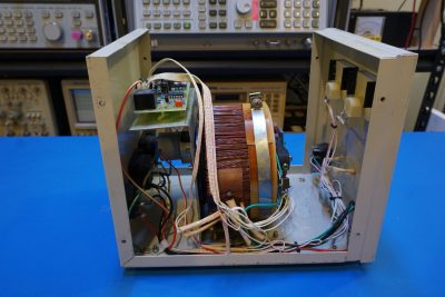
The ATVR-1000D utilizes a motor to drive the wiper of a autotransformer (Variac), the servo motor can be driven in either direction depending on the output from the OpAmp (LM324) based comparator. Comparing to a voltage regulator that uses relays for tap-switching, this type of servo-driven voltage regulator has several advantages. It offers continuous voltage adjustments as opposed to the limited discrete steps offered by relay-switching regulators. Also the output waveform is continuous. As unlike relay switching in which the contacts were disconnected first before a different tap was chosen, the carbon wiper maintains contact with the transformer coil at all times. The main drawback of this kind of motor-driven voltage regulator is that its reaction speed is relatively slow (the rated response time for the ATVR-1000D is 1.5 sec) due to the mechanical constraints. Thus it is only suitable for maintaining slow-varying line voltages.
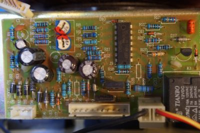
Here is a picture of the controller board. As mentioned before, the onboard LM324 compares the line voltage to a Zener reference and controls the motor rotation. It also has a time delay circuit builtin so that when powering on, the regulator has a chance to stabilize the output before the output is connected. There is also an over-voltage detection circuit that triggers the relay to disconnect the output should the output voltage rises beyond a maximum threshold. This can happen when the line voltage rises rapidly, since the mechanical movement of the wiper takes time to settle, the output could shoot up beyond the safe limit for a short duration. And when this happens, the output relay is disconnected momentarily so that the connected devices would be safe.
The power to the controller board is provided via a secondary winding on the toroidal transformer.
The stabilized output voltage can be adjusted via the top potentiometer in the picture above. By tweaking its value, I managed to adjust the output voltage from a nominal 110V AC to 120V AC. The other potentiometer is likely for adjusting the over-voltage trip point.
In the pictures below, you can see a closeup of the transformer and the wiper contact. In the picture to the left you can see a momentary switch which is the limit switch for the under-voltage panel indicator. There is another momentary limit switch on the other side and is engaged when the upper adjustment limit is reached and in this case the front panel over-voltage indicator is lit and the output is disconnected. Note that this over-voltage situation is different than the transient input voltage jump caused over-voltage we discussed earlier.
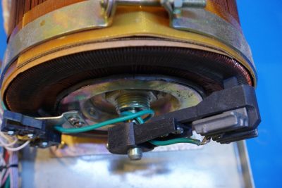
|

|
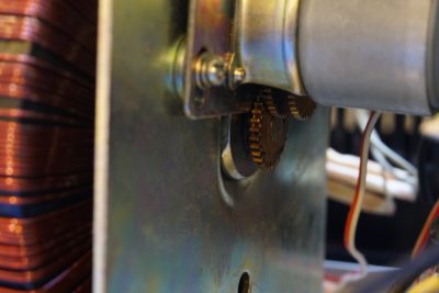
Here is a closeup picture of the mechanics of the servo motor. You can see several speed reduction gears, which are used to increase the torque so that the relatively small motor can be used to rotate the rather hefty shaft.
In the video below, I discussed the principle of operations of different typess of AC voltage regulators alone with a teardown of this ATVR-1000D regulator.
