For those who are following my YouTube channel, you would know that I am in the process of building a high capacity battery bank. When this project is done, I plan to use it with a 12V inverter as my backup generator in the event of a power failure. For the battery bank, I used eighty 3.2V 5.5Ah 32650 lithium iron phosphate (LiFePO4) batteries. These are arranged into 4 groups in series and each group consists of 20 cells paralleled together forming a 12.6V 110Ah battery bank.
Like lithium ion batteries, lithium iron phosphate batteries require proper battery management system (BMS) to protect cells from overcharged or over discharged and also to ensure voltages among the cells in series are properly balanced. For my project, I decided to use an inexpensive off-the-shelf LiFePO4 BMS module. Since I intended to use the battery bank for a maximum load of around 1kW, I would need a BMS that can handle at least 80A discharge current continuously. And to charge the 110Ah battery bank, the charging current the BMS module must be able to withstand should be at least 6A (at C/20 rate).
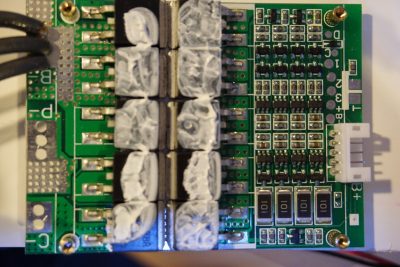
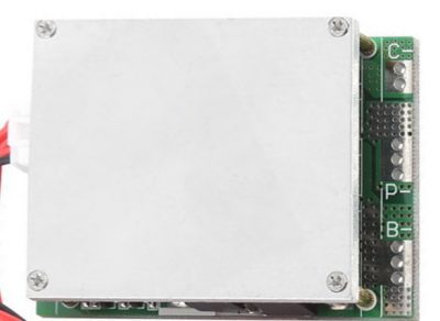
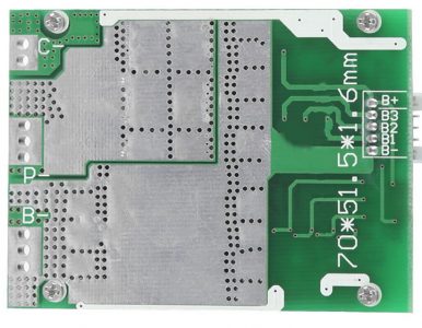
Based on these requirements, I found this 4S LiFePO4 BMS module on eBay (see pictures below). It is rated for a continuous discharge current of 100A and has a maximum charge current of 10A which is perfect for what I needed if these specs prove to be accurate. The only issue is that the balancing current this unit provides is only 36mA which is way too small for a 110Ah battery bank. But for $8 I was willing to give this module a try and hopefully I could modify it for higher balancing current.
|
|
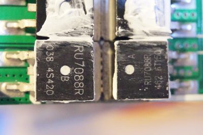
From the pictures above, you can see that the circuit board of the module is actually very well designed. By the look of the plated traces and heavily stitched power and ground planes, I have no doubt that this this board would be able to withstand the rated current. The picture below shows the MOSFETs on the circuit board with the top heat spreader removed. The thin aluminum plate probably wouldn’t help that much in terms of dissipating heat especially given that it is mounted on the wrong side of the MOSFETs. But given that these MOSFETs are for switching operation only, the power dissipation should be pretty low anyway.
By looking at how the power plane splits, it appears that six or seven of the overall ten MOSFETs are responsible for the discharge current path and the remaining two or three are responsible for the charging current path.
The MOSFETs used here are Shenzhen Ruichip‘s RU7088R N-channel MOSFETs. According to the datasheet, the MOSFET has a Rds(on) of 6.5mΩ and an Ids of 40A. Spec-wise, these MOSFETs should be more than adequate for the job. Assume that there are seven MOSFETs sharing the load, at the maximum rated current, each MOSFET should only be dissipating roughly 1.3W (assume current is evenly shared among all seven MOSFETs. The power dissipation of each MOSFET is 14^2*0.0065).
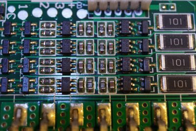
From the high resolution picture below, you can see that two different types of SOT-23-6 ICs are used. The ones marked 12CB K607 are Hycon Technology‘s HY2112-CB single cell LiFePO4 battery protection ICs. The CB model has an overcharge detection voltage of 3.75V and over discharge detection voltage of 2.1V. If I were to build the protection circuitry myself, I would have chosen the HB model instead as it has a less aggressive over charge detection voltage of 3.65V and over discharge detection voltage of 2.5V. Altogether there are four HY2112-CB’s, one for each battery bank in series.
The other four SOT-23-6 chips (marked AB3A K602) are Hycon Technology’s HY2212 single cell LiFePO4 battery pack charge balancing ICs. From the picture below, you can see that the output from each HY2212 drives a HM2302A MOSFET (the marking is A2SHB), which is made by Shenzhen H&M semiconductor.
Now it is clear where the 36mA balancing current mentioned in the BMS datasheet comes from. When battery overcharge is detected, the connected MOSFET to HY2212 is turned on and the load resistor (100Ω) is connected across the battery to slowly discharge it so that other batteries connected in series can have a chance to catch up. Since HM2302A is capable of switching up to 2.9A, we can easily increase the balancing current by decreasing these 100Ω load resistors.
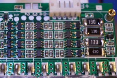
To reduce the load resistance, I paralleled a 13Ω resistor with each of the 100Ω resistor (see picture below). The end result is a 11.5Ω balancing resistor for each 110Ah battery bank. This corresponds to a balancing current of 313 mA. While I could increase this current even further since HM2302A can easily handle quite a bit more, I am mainly limited by the existing footprints on the PCB and thus the power dissipation of the resistors. While 300mA doesn’t sound like much compared to the 110Ah capacity of each battery bank, it should be able to properly balance these battery banks given that their charge states are similar. This is usually the case for batteries coming from the same batch.
