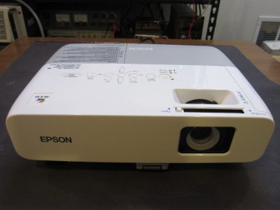
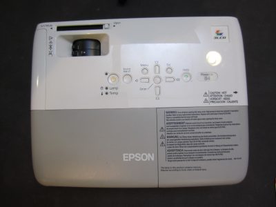
I recently was given a broken Epson PowerLite 84 projector. The projector would not turn on when plugged in and there was no sign of life. So I decided to take a look at what was wrong with it. The potential reward is high since I do not have a projector yet and I could definitely use one for my home theater setup. A video of this teardown and repair is linked towards the end.
Although the Epson PowerLite 84 series multimedia projectors had been discontinued for a long while, it remains relatively modern as far as technology goes. Mine seems to be in very good physical shape. If I were to guess, I would say it was probably made within the last 10 years or so.
|
|
The PowerLite 84 series use 3LCD technology, using three separate LCD chips to form an image of each color component and then combine these monochromatic images of each RGB component together to form the final color image. This is different than the SMART UF55 DLP projector I did a teardown with a few weeks ago. A DLP projector uses a micro-mirror device along with a spinning color wheel, and at any given time because the color wheel spins at a high speed the resulted image appears to be in color due to the effect of persistence of vision.
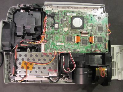
The construction of the PowerLite 84 is quite compact for the amount of components inside, this is evident from the picture below.
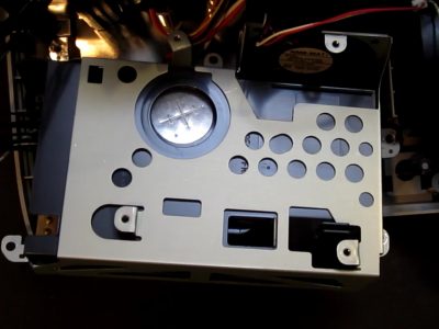
Because the discharge lamp generates quite a bit of heat during operation, the internal layout must be carefully engineered to make sure sensitive components are not subject to excessive heat.
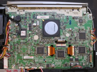
As can be expected, the integration level is generally quite high for these consumer projectors. Unfortunately, I couldn’t find any information on many of the ICs. But most of the video processing is likely happening inside the Pixelworks SoC. The datecodes on some of the components suggest that this projector was made sometime after 2009.
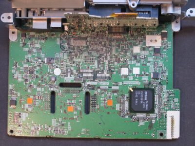
Here is a picture showing the bottom side of the main board. Again, besides the single Epson chip (I couldn’t find any information on it), there are only a few local power regulator circuits.
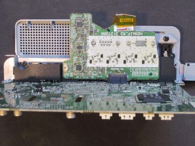
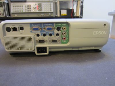
There is a vertical peripheral board connected to the main board via board-to-board connector. The vertical board houses all the rear-access connectors.
Because the unit does not power on at all, the power supply becomes the primary suspect. One thing I am certain is that the fuse (at least the fuse on the mains side) remains intact as there is measurable amount of current flowing through the projector when it is plugged in.
Also, I measured the supply voltages on the main board at the input connectors and I could not get any readings there. So clearly the switching power supply board had failed. In order to further diagnose the issue, I had to first get access to the power supply board.
Power supply failures are very common in electronics as they typically suffer most of the stress (high current, high temperature, etc.). However, if designed properly, power supply failure should be well contained within the power supply itself and should not have damaged anything else. But sometimes, especially when protection circuitry is not adequate, large transients could be generated before the output was clamped or disabled. And if this is the case, it could be particularly problematic as the ICs on the power rail would likely have been damaged.
Anyway, I am hoping that the failure is limited to the power supply itself as any damage to the sensitive ICs on the main board means that the chance of reviving this projector is nil.
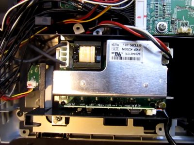
Unfortunately, the power supply board was tucked at the bottom below the metal shielding, underneath the ballast board. In order to get to the power supply board, I had to first remove the shielding, and then remove the ballast board on top. The picture below shows the ballast board.
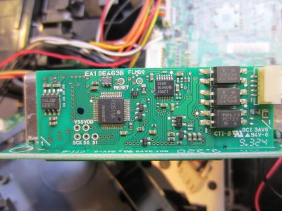
Here’s a picture showing the controller daughter board on the ballast.
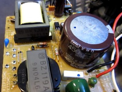
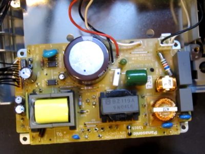
And the picture to the left below shows the switching power supply assembly. The picture on the right is the switching power supply board. Only few components are located on the top of the board. The MOSFETs are soldered on the reverse side and mounted on a heatsink plate which covers the entire underside. Unfortunately, this layout makes it very difficult to service the active components underneath should there be anything wrong with them as the heatsink plate is also soldered on to the circuit board.
At a first glance, everything looked pretty normal. There is no bulging capacitors, no open fuses and no signs of any MOSFET damage.
|
|
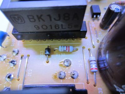
But while testing the resistors, I noticed that R130 was open circuit while it should be 2.2Ω. A closer look (see image below) shows that the side of the resistor had cracked and a piece of the conducting material might have come off. Given the low value of the resistor, it could be on the current sensing path of the power supply. Clearly, this would have contributed to the symptom we saw earlier.
Because it is almost impossible to desolder the resistor without having to remove the soldered-on heatsink plate on the other side of the PCB, I decided to just solder a replacement resistor in place. This is possible since the original one is open.
This picture shows the replacement resistor soldered on top of the original resistor.
And the projector came back to life again! In the video below, you can see this repair in a bit more detail:
