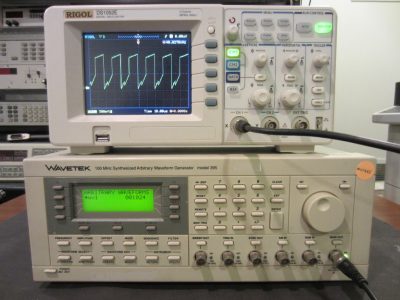
I picked up a Wavetek 395 arbitrary waveform generator on eBay a few weeks ago. Wavetek 395 is a single channel, 12-bit resolution DDS AWG with a maximum clock frequency of 100 MHz. While the operation manual is readily available, I could not find the service manual anywhere. So I was curious to see the construction inside. In this post, I will show you some of the teardown pictures. If you want to see a video of the teardown along with some analysis, you scroll towards the end of this post.
From the datecodes on various components we can tell that This AWG was made sometime between the late 1990’s and early 2000’s. Although it is more than 15 years old, it’s specifications compare quite well with a modern AWG like the Rigol DG2041A or a Keysight 33250A. Although most modern AWGs support more advanced modulation schemes (such as BPSK, QPSK, OSK, etc.). But for hobby use, Wavetek 395 is more than adequate.
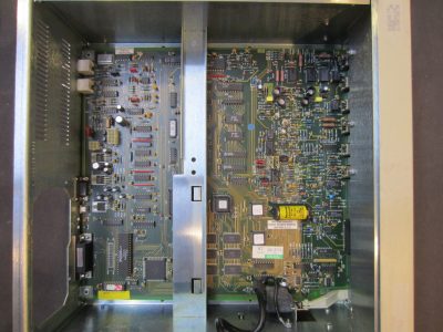
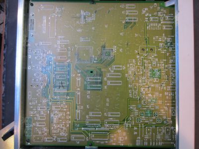
Here are a couple of pictures showing the top and the bottom of the PCB upon opening the case and removing the switching power supply. A single 4-layer PCB is used in this AWG. Since all components used are through-hole, everything is populated on the top layer only. The inner layers are for the power and ground planes. For high speed circuit, this kind of ground and power plane arrangement can reduce unwanted noise significantly.
|
|
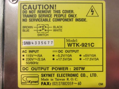
The power supply used is an off-the-shelf switching power supply with a 5V and -5.2V rails and ±17.5V rails. The power supply is rated at 207W, which is more than adequate for the AWG. During my limited testing, the actual power consumption never exceeded 50W. Like many older switching power supplies, this one does not have any power factor correction (PFC) circuitry and thus the power factor is quite poor at around 0.6.
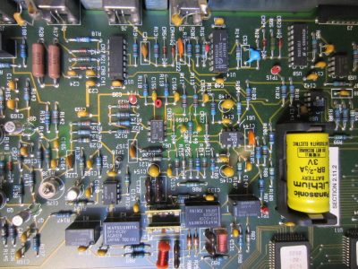
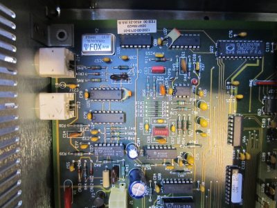
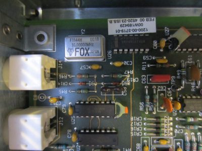
The main clock crystal used in Wavetek 395 is a FOX F1144H series 10 MHz oscillator. With a frequency stability of 100 ppm, it is not a superb frequency reference by any means. But you can always use an external more accurate clock source if more stability is needed. From the pictures below, you can see a MC1648 VCO, which is most certain used in a PLL circuit to synthesize the variable clock frequencies required for the arbitrary waveform generation.
|
 |
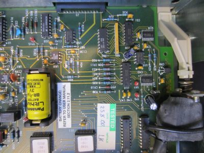
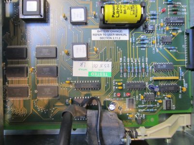
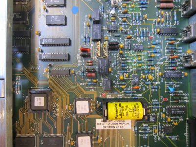
In the picture to the left below, you can see 6 TC551001 chips. These are 128kx8 SRAM chips. Together they provide the 256k points waveform memory needed for the waveform generation. This unit is equipped with option 1 (256k-point waveform memory), and the standard configuration has only 64k points waveform memory. The content of the waveform memory is backed up with a Lithium battery.
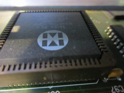
You can also see a few EPROMs in the picture, these are presumably for firmware and calibration data storage. In the picture to the right below, you can see a Wavetek branded chip. I could not find any information on it, but it is most likely a custom ASIC for some AWG logic.
|
 |
In the close-up picture below, you can see a LT1004 2.5V voltage reference sitting underneath the mains power switch. And there are two general purpose 12bit DACs (MB88351) in the vicinity. Given their relatively limited performance (2.5MHz) and their proximity to the voltage reference, my guess is that they are probably used to generate some required reference voltages.
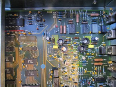
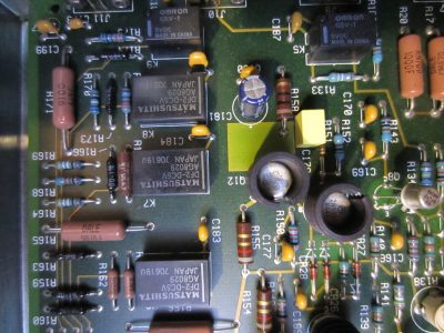
Below are a couple of pictures showing the output portion of the circuit. High speed transistor pairs 2N5943 (NPN) and 2N5583 (PNP) are used to form the push-pull output stage. You can also see many relays for switching various signals. The chip tucked in the upper left corner in the image to the left is an AD9712 12-bit 100 MSPS DAC, an ECL compatible fast digital-to-analog converter. This is the main converter that drives the output stage. Because it uses ECL logic, there is a 100329PC ECL/TTL bidirectional translator chip below it.
|
|
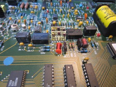
In these pictures, you can see two custom filter packages mounted on ceramic bases.
|
|
Here you can see an AD834 a 500MHz four quadrant multiplier. And CLC409 is a wide-band low distortion operational amplifier.
Power from the main switching power supply unit is further regulated via the on-board linear regulators. A few MC10H125 quad MECL to TTL translator chips can also be seen here.
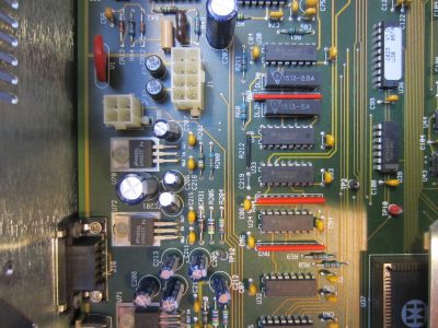
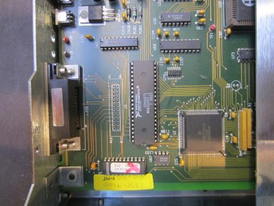
The microcontroller used in the Wavetek 395 is an MC68331CFC16 32bit M68000 compatible microcontroller. You can still buy these MCUs on DigiKey today and they are quite expensive, costing more than $30 each. The unit I got also comes with the GPIB option, so you can also see the scoketed NI IEEE-488 controller chip below.
