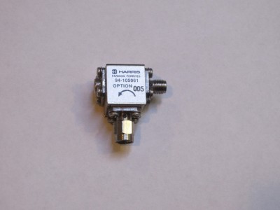
I did a teardown video of a microwave range (8-10 GHz) RF isolator last week. As a follow up, I will post some of the high-resolution pictures I took during the process here (click to see larger images).
If you haven’t watched the video, I would recommend you watch it first. In the video above, I did a detailed teardown along with some experiments.
This is the 50 Ohm termination cap. The termination resistor in the middle is a carefully constructed hollow cylindrical resistor. In the picture to the right, potting compound was carefully removed.
|
|
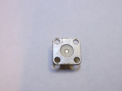
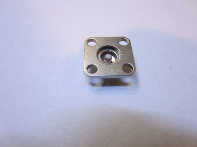
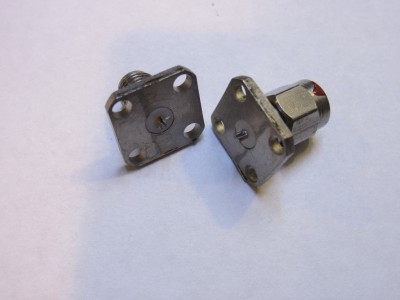
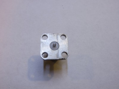
These are the two SMA connectors. The center pins are clipped onto the center copper disc.
|
|
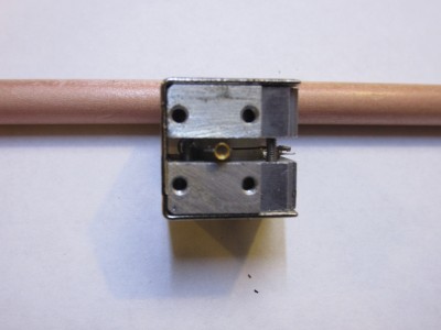
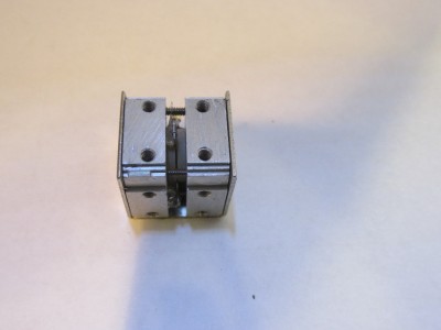
Here you can see the two aluminum blogs holding the two ferrite discs. Sandwiched between the discs is the copper piece where the termination resistor, input and output SMA connectors are mounted. In the picture on the left hand side below, you can see the hollow cup that mates with the 50 Ohm resistor. It was designed to ensure minimum reflection across the designed operating frequencies.
|
|
The magnetic field perpendicular to the ferrite discs is generated via two circular magnets in the cavities of the aluminum blocks on either side. The magnetic field strength impacts the characteristics of the isolator directly and thus must be tuned individually for each isolator in production. The two metal discs are likely used to adjust the distances between the two magnets to achieve the desired field strength precisely.
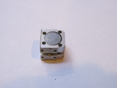
|
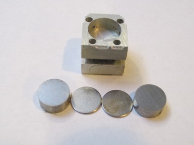
|
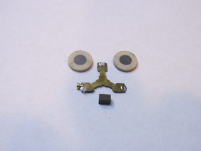
Here the top aluminum block is removed. In the left picture, you can see the metallic back side of the ceramic disc that holds the ferrite material. Towards the right, you can see the copper conductor on top of one piece of ferrite core ceramic disc and the other ferrite core ceramic disc is on the side. The edges mating with the resistor and the SMA connectors are silver coated. There is also a small ferrite block (black) on the side of the discs. I think it might have been used to fine tune the magnetic field.
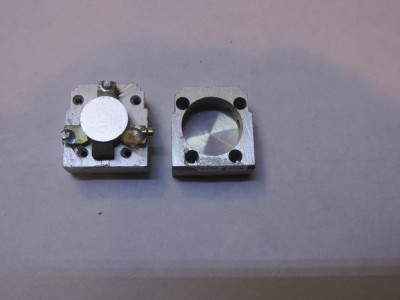
|
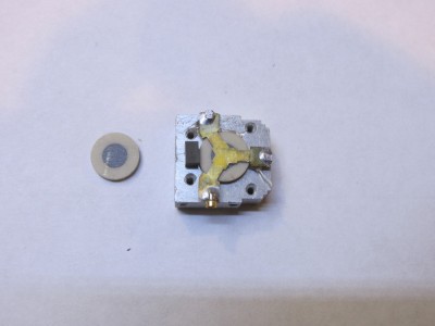
|
Here is a picture showing the remaining pieces dissembled.
