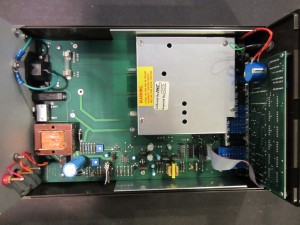
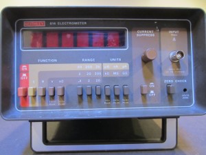
In this blog post, we will take a look inside a 1980 vintage Keithley 614 Electrometer. While it was designed and built more than three decades ago, its performance is still pretty impressive (10 fA current resolution) even compared with today’s modern standards. Its performance was only rivaled by Keithley 617 in its days.
Opening up the case is very straightforward, involving only the removal of two screws at the back of the instrument.
|
|
The circuitry inside is fairly sparse as the meter is mostly analog and the only digital portion is for the display circuit located on the vertical board for the front panel. Note that the lead-acid battery block had been removed in this meter. A few of Keithley’s models back then (e.g. Keithley 177) also used lead-acid battery packs. These battery packs add significant weight to the unit and had a pretty short life span. Anyway, the battery pack is totally optional and does not interfere with the operation of the meter. It would not be too difficult to replace the battery pack with a Ni-Cd or Ni-MH type (6 or 7 cell) however. The battery monitor circuit on the 614 uses an Intersil ICL8211 programmable voltage detector to set the charge and deplete voltage levels and you can easily adjust the corresponding trim pots to accommodate different backup battery voltages and chemistries.
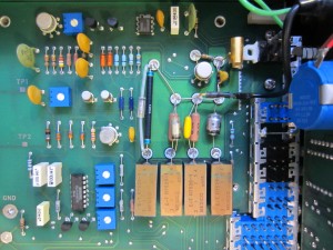
The circuitry responsible for its low current measurement performance is hidden underneath the metal shielding. And the picture below reveals the circuits inside. Note the Teflon insulated solder cup standoffs in the middle. This is necessary in order to achieve the femtoamp performance. At this current level, the leakage current in the PCB material can no longer be ignored. It is also extremely critical to keep this section of the board clean.
Since this board uses through-hole components exclusively, there probably isn’t anything interesting on the other side of the board so I didn’t bother taking the board out. But I suspect there are quite a few guard traces between the high impedance paths to further eliminate leakage current. You can see one such guard trace in the picture below (around the resistor next to the bottom of the first relay on the left). The zero check switch is essentially just a piece of copper in contact with a piece of bare wire. The reason for this is also to ensure minimum current leakage.
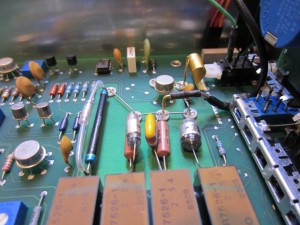
Here is a picture of the same front end circuit from a different angle. You can certainly appreciate the thoughts put into the design.
Given the femtoamp current resolution, I was expecting to see some extremely high spec’d Op Amps. But surprisingly most of the Op Amps used here are quite ordinary (AD741, LM308, LM343). There is only one precision chopper stabilized Op Amp in use (ICL7650, 1µV input offset voltage, 10pA input bias current) in its ranging circuit. But the front end only uses an LM308 and a matched JFET pair. The exact spec was not given for the matched JFET pair. I suspect that they are hand picked to meet the tight specifications.
Keithley 614 requires a low noise, unterminated 2-lug triax cable for its input. This kind of cable is pretty rare these days as the standard triax cables are 3-lug versions. If you intend to use a triax-BNC converter, make sure that the outer shielding is not terminated to the inner shielding.
