I recently acquired an old Beseler PM2L color analyzer. This kind of color analyzer was designed to analyze the color or exposure of film negatives at a certain location by comparing the intensity of the filtered light of each color channel (CMY and white). The PM2L model was made in the 70’s through early 80’s and has long become obsolete. But since it has a 931A photomultiplier tube (PMT) inside, you can easily repurpose it for other uses. And the good news is, these old color analyzers are cheap on eBay. You can usually grab one for a price cheaper than a bare PMT itself.
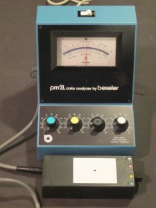
Here is a picture of the PM2L color analyzer I got. The cap for the magenta adjustment knob is missing. The black box in the front is the light sensor which houses the photomultiplier tube.
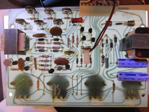
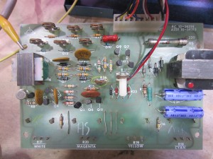
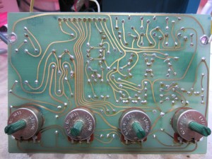
Don’t be fooled by the relatively large size of the instrument. The circuitry inside is actually quite simple. Everything is soldered on a sparsely populated single-sided PCB. The four adjustment potentiometers are mounted on the reverse side of the board.
|
|
The PMT is housed inside a black plastic instrument box as shown earlier. The box is designed to be light-tight (the lid is mated tightly against the walls, you will need to pry it open carefully).
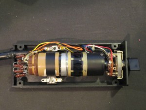
The picture on the left below shows everything inside the housing. The cable comes in from the left hand side, The PMT is housed inside a metal which provides proper magnetic shielding. The metal can is grounded via a bare wire in contact with the can exterior. Color filters are mounted on the side of the shielding can. The shaft of the color-selection rotary switch is connected directly to the can so that whenever a color is selected, the corresponding channel circuit is connected and the color filter for that channel would be applied to the PMT opening.
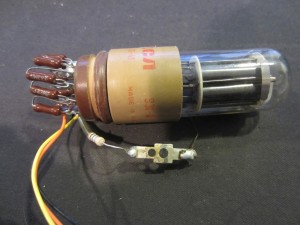
The PMT used here is a RCA 931A (side-on). It was the first commercially mass produced PMT and it is still in production today.
|
|
I was curious to see how this analyzer works. But after combing the Internet, I could not find any schematics available. So I decided to reverse engineer the circuitry from the PCB myself.
One of my favorite methods for reverse engineering a single layer or double layer board is to first place the PCB on top of a light box. Then I would place all the components with the same relative locations on the PCB using a layout editor (e.g. Eagle). Once the components are placed I then would follow the PCB traces and connect components together.
Here is a picture of the PCB on top of a light box, you can clearly see the traces on the reverse side.
Here is the first cut of the schematic, every component is placed where they appear on the board so the connections can be easily verified.
Here is the final schematic with some simplifications (e.g. diodes connected in series to increase breakdown voltage are replaced with a single diode):
Judging from the circuit, here is how it works (please correct me in the comment below if you find anything wrong). Q1-Q6 and Q11 form an inverter and associated control circuitry. The inverted voltage is doubled via a voltage doubler and the output voltage goes through a current limit resistor (R3) and then goes to the cathode of the PMT.
Because the brightness in photo negatives can vary dramatically, the photometer is designed with a logarithmic response via the potentiometer/diode network in the upper left of the schematic (for more detailed explanations, please refer to Photomultiplier Handbook).
Q7-Q10 are used to drive the output differential voltmeter.
The four potentiometers in the bottom right corner of the schematic are the null-adjustment pots for the cyan, yellow, magenta and white channel. Each control is independent of the others and they are wired into the sensor box and are switched by the selector switch along with the color filter mechanism as we saw earlier.
All resistors in the voltage divider for the photomultiplier are 3.3M’s. Given the high value resistors used, this detector is only suitable for detecting very dim light exposure as increased anode current will degrade the PMT output linearity significantly.
Because of these high value resistors between the dynodes, measuring the PMT supply voltage becomes a bit tricky as most high voltage probes have less than 100MΩ input resistance and can cause significant load on the HV generator and thus skew the measurement. The measured result puts the supply voltage at just above 600V, which is surprisingly low for the 931A photomultiplier (a typical supply voltage would be around 1,000 V). Although higher voltage can improve sensitivity dramatically, I suspect that the sensitivity level must be good enough for a color analyzer. Anyway as you can see in the video later, the analyzer is already extremely sensitive the way it is.
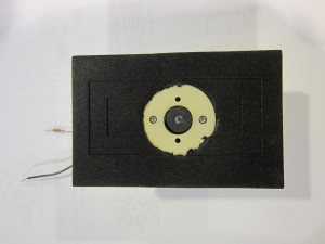
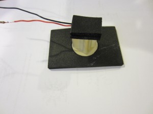
Inspired by Mike’s video, I decided to take a look at the sensitivity of this photomultiplier with the default circuitry. For the experiment, I made a lightproof enclosure for the LED (see pictures below). A blue LED is used as the light source. The reason I chose a blue LED is because that 931A’s spectral response peeks in the ultraviolet to blue light region. In the video below you will see that the entire cylinder is wrapped with multiple layers of the black foam material to make sure that light does not go into the sensor aperture from the outside. To increase sensitivity, I removed the white light diffuser on the sensor shielding can so that light can go into the photomultiplier window directly when the selector is switched to white. I also modified the color analyzer a little bit by adding a switch at the differential meter so I could either use the meter as is or measure the output voltage directly.
|
|
The minimum current required to produce light discernible by naked eye is at around 3µA for the LED I used. The following table shows the resistors I used versus the measured differential output voltage (calibrated to roughly 0V when LED is off).
| Resistance (MΩ) | LED Current (µA) | Output Voltage (V) |
|---|---|---|
| 2.2 | 1.3 | 0.85 (saturated) |
| 12.2 (2.2+10) | 0.25 | 0.41 |
| 22.2 (2.2+10+10) | 0.13 | 0.21 |
As you can see, the result is pretty linear. While I do not have a 100MΩ resistor like Mike did in his experiment, by interpolation we can see that even with a 100Ω resistor the output light from the blue LED is still detectable. And by increasing the voltage applied to the PMT, we can increase the sensitivity even further.
Below is a video of the experiment.
|
View on YouTube in a new window |
