Ever since I got my HP 436A power meter, I have been looking around hoping that I could obtain a compatible power sensor (e.g. 8484A) at a reasonable price to go with it. But these power sensors are quite expensive on the second-hand markets and even a non-functional unit can cost more than a hundred dollars. Since like most hobbyists, my requirements for a power sensor is not that high, I decided to build a simple RF power detector myself.
The detector chip I used is a Linear Technology LT5534. It covers the 50 MHz to 3 GHz frequencies with a dynamic range of 50 dB. Originally, I wanted to use an Analog Devices AD8312 which covers roughly the same frequency range (50 MHz to 3.5 GHz) that I am interested in. Dynamic range wise AD8312 is 5 dB worse than LT5534, but it is far cheaper. The only problem is that AD8312 is only offered in the tiny WLCSP packaging (Wafer Level Chip Scale Packaging) which is pretty difficult to work with as the packaging is leadless (similar to BGA). LT5534 on the other hand comes in SC-70 package which is much easier to handle.
For the build, I followed LT’s reference design detailed in the datasheet. For the output filtering, I used a 2.2K/10pF output RC filter to limit the output bandwidth to around 3 MHz.
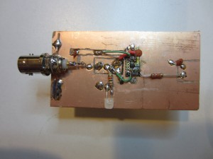
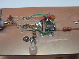
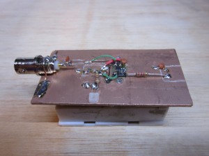
Since we are in the RF realm, board layout becomes much more critical than dealing with sub MHz circuits. But for the prototype, I used a piece of FR-4 PCB and routed a few islands for the power, input and output. This leaves us with a large contiguous ground plane which is critical in lowering ground inductance. The LC5534 chip is mounted on a trimmed adapter board, which is then glued onto the PCB’s ground plane. The wiring is kept as short as possible to minimize unwanted coupling. I used a BNC connector for the input. Since the maximum frequency LT5534 can handle is 3 GHz, a BNC connector should be sufficient. The BNC input is terminated right at the input. A RF rated surface-mount 47 Ohm resistor would have been ideal here but I used a nominal 50 Ohm (measured 47 Ohm) 1/16 W carbon film resistor instead as it’s the only kind I have on hand.
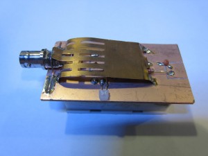
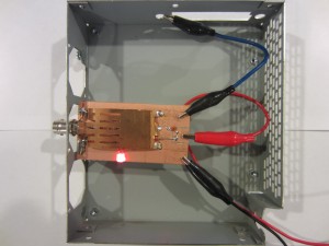
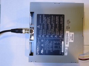
The circuit is powered by two AA batteries, which are placed in a battery holder mounted on the reverse side of the board. To reduce interference, I soldered on a piece of copper sheet over the sensitive detector chip. I also added a switch and a LED indicator so that I can easily turn the unit on and off. Here are a few pictures of the build:
|
|
|
|
Because the circuit is extremely sensitive to environmental electromagnetic interference, in order to achieve the lowest noise floor I placed the entire circuit inside a metal case during the characterization process. When there is no input, the output voltage is at around 0.3 V which is within the 0.142 V to 0.380 V range specified in the datasheet.
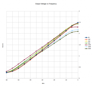
The first figure below shows the relationships between the output voltage and the input power under different frequencies. I used my HP 8642B to generate the input signal. The power is stepped from -60 dBm to 0 dBm in 5 dBm increment. The characteristic curves are measured for seven representative frequencies (50 MHz, 100 MHz, 200 MHz, 500 MHz, 1GHz, 1.5 GHz and 2 GHz). These curves largely follow the typical performance characteristics shown in the datasheet.
|
|
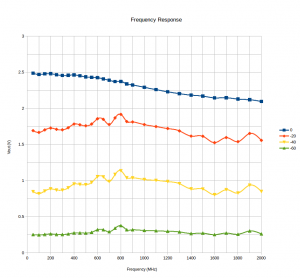
The second figure shows the flatness of the response when the input sweeps through the entire frequency range at different power levels (0 dBm, -20 dBm, -40 dBm and -60 dBm). Ideally, they should be close to flat lines. But the measured results are not quite as smooth. By analyzing the data, we can see that the 0 dBm line is pretty close to the ideal response curve (the non-linearity increases with the power level and input frequency). The -60 dBm response is also pretty close to the ideal curve. The curves for -20 dBm and -40 dBm exhibit some peaks and valleys below 900 MHz and above 1.4 GHz however.
|
|
There could be a few contributing factors. For instance, the reflection coefficient of the cabling and the SWR may be frequency dependent especially given the average-quality coax I used. Also, the frequency response of the RF attenuators in the HP 8642B may not be totally flat. I wouldn’t be surprised as this unit was probably last calibrated more than a decade ago. Last but not least, the crude board setup may also have been a contributing factor.
Nevertheless, we can still use this detector to make rather accurate measurements once we have characterized its performance.

