I just got myself a couple of Arduino Due boards. While they were released almost two years ago, I have not really got a chance to look at these until quite recently. Arduino Due is based on Atmel’s ATSAM3x8E 32-bit ARM Cortext-M3 processor. The processor core runs at 84 MHz, which is significantly faster than its 8-bit AVR counterpart ATmega328p which runs at 16 MHz. For an ATmega328p, the highest achievable PWM frequency is 8Mhz (square wave), so we should be able to generate much higher frequency signals on an Arduino Due. But how high can we go? Let’s find out.
If you use the bit-banging method (e.g. pin toggling), the highest achievable output frequency is actually quite abysmal. For example, the following code on Due generates a 200.7 kHz square wave on pin 8 (compiled with Arduino 1.5.7):
#include <Arduino.h>

void setup() {
  pinMode(8, OUTPUT);
}

void loop() {
  while (true) {
    digitalWrite(8, HIGH);
    digitalWrite(8, LOW);
  }
}
The Arduino code base is not very efficient and this code is actually not much faster than the same code on an ATmega328p (126.2 kHz for comparison, compiled with Arduino 1.0.5). By the way, the reason a while loop is used inside the loop() function is that the loop function has some extra instructions for checking the serial port. So if we did not use the while loop, extra instructions would be executed after outputting a LOW, causing the duty cycle to change and lowering the overall waveform frequency. This overhead is not very noticeable on ATmega328p (116.9 kHz without the while loop versus 126.2 kHz with the loop). But on Arduino Due, this difference is much more drastic. If the while loop is removed, the output frequency will drop to 145.4 kHz which is a 30% degradation from 200.7 kHz!
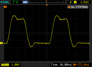
Of course, we can improve the code efficiency above quite a bit by using direct port manipulation. If we replace the digitalWrite with the following code, we will get an output square wave on pin 8 of roughly 16.8 Mhz. This is a huge improvement over the meager 200.7 kHz with digitalWrite.
    g_APinDescription[8].pPort -> PIO_SODR = g_APinDescription[8].ulPin;
    g_APinDescription[8].pPort -> PIO_CODR = g_APinDescription[8].ulPin;
We can do even better if we use the dedicated hardware (e.g. via PWM controller) to generate our waveform rather than big-banging with software. But before doing that, let’s take a look at how the the 84 Mhz clock frequency is obtained on the Due.
Under the hood, Arduino IDE uses Atmel’s CMSIS compliant libraries. They source code and binaries are located under /arduino-1.5.7/hardware/arduino/sam/system/ with the Arduino IDE distribution.
In /arduino-1.5.7/hardware/arduino/sam/system/CMSIS/Device/ATMEL/sam3xa/source/system_sam3xa.c you will find the following definitions:
#define SYS_BOARD_PLLAR (CKGR_PLLAR_ONE \
                       | CKGR_PLLAR_MULA(0xdUL) \
                       | CKGR_PLLAR_PLLACOUNT(0x3fUL) \
                       | CKGR_PLLAR_DIVA(0x1UL))

#define SYS_BOARD_MCKR (PMC_MCKR_PRES_CLK_2 | PMC_MCKR_CSS_PLLA_CLK)
SYS_BOARD_PLLAR defines the PLLA clock with a multiplier of 0xd (13). Since the master clock (MCK) frequency is derived as (MUL+1)/DIV multiplied by the PLL frequency the result of the master clock frequency is 12*(13+1)/2=84 Mhz.
The hardware PWM related functions are in /arduino-1.5.7/hardware/arduino/sam/system/libsam/source/pwmc.c, and the power management controller code are in /arduino-1.5.7/hardware/arduino/sam/system/libsam/source/pmc.c.
If you take a look at the function PWMC_ConfigureClocks in pwmc.c, you will see that the highest PWM frequency can be accommodated as the function input is 42 MHz, this is because inside the function it calls FindClockConfiguration which in turn ensures that the frequency parameter passed in is less than the MCK frequency. Thus for integer dividers, the highest frequency we can pass in is 42 MHz (with divider 2).
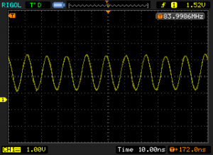
To achieve the highest output frequency, we can use a one bit PWM which essentially just outputs a square wave with a duty cycle of one. We can then set the prescaler to 2 to obtain an 84 MHz waveform.
#include <Arduino.h>

uint32_t pwmPin = 8;
uint32_t maxDutyCount = 2;
uint32_t clkAFreq = 42000000ul;
uint32_t pwmFreq = 42000000ul;

void setup() {
  pmc_enable_periph_clk(PWM_INTERFACE_ID);
  PWMC_ConfigureClocks(clkAFreq, 0, VARIANT_MCK);

  PIO_Configure(
    g_APinDescription[pwmPin].pPort,
    g_APinDescription[pwmPin].ulPinType,
    g_APinDescription[pwmPin].ulPin,
    g_APinDescription[pwmPin].ulPinConfiguration);

  uint32_t channel = g_APinDescription[pwmPin].ulPWMChannel;
  PWMC_ConfigureChannel(PWM_INTERFACE, channel , pwmFreq, 0, 0);
  PWMC_SetPeriod(PWM_INTERFACE, channel, maxDutyCount);
  PWMC_EnableChannel(PWM_INTERFACE, channel);
  PWMC_SetDutyCycle(PWM_INTERFACE, channel, 1);

  pmc_mck_set_prescaler(2);
}

void loop()
{
}
Note that VARIANT_MCK is defined in /arduino-1.5.7/hardware/arduino/sam/variants/arduino_due_x/variant.h as 84000000. PWM_INTERFACE_ID and PWM_INTERFACE are defined in variant.h as ID_PWM and PWM which in turn are defined in /arduino-1.5.7/hardware/arduino/sam/system/CMSIS/Device/ATMEL/sam3xa/include/sam3x8e.h.
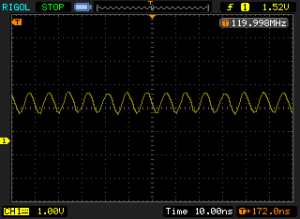
If we change the prescaler value to 3, in theory we should get a 126 Mhz waveform. But this timing is not supported and while you do get a brief output burst of signal in the desired frequency range (see last picture below), the waveform quickly becomes unstable.
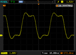
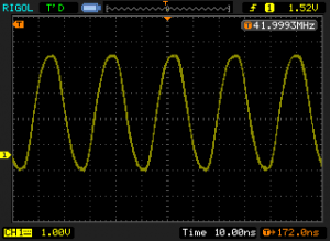
So as the conclusion, the highest stable frequency we can generate using an Arduino Due is 84 MHz. The pictures below show the captured waveforms under different frequencies. For the 21 MHz waveform, pwmFreq is set to 21000000, no prescaler is used. For the 42 Mhz waveform, pwmFreq is set to 420000 with no prescaler. The 84 MHz waveform is generated with
|
|
|
|
