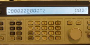
If you take a look at the picture below, you may recognize immediately that it is a picture of an HP 8642B synthesized signal generator. But if you take a closer look, you probably will notice something different if you have ever used an HP 8642B before.
The original HP 8642 series used two miniature incandescent light bulbs for the instrument LCD backlight and the backlight has an orangish color to it. Unfortunately these light bulbs do not last that long (a few hundred hours) and if you got a used HP 8642 chances are that the backlight no longer works. This is exactly what happened to my HP 8642B. Unfortunately, without the backlight the instrument display is pretty difficult to read. So I decided to open it up and change the backlights.
HP 8642 was introduced in the late 80’s (mine was made in 1987) and it was one of the most advanced synthesized signal generators on the market back then. Because it weights a ton (more than 70 lb), people generally shy away from them especially when purchasing online since just shipping alone could cost a fortune. But if you ever get your hands on one, you will fall in love with it immediately.
HP 8642 is a step-up from HP 8657, a more popular choice among the hobbyists due to its availability and lighter weight — about 20 lb lighter than 8642. Comparing these two models, HP 8642B has a frequency range from 100kHz to 2115MHz and HP 8657B’s range is between 100kHz and 2060MHz. HP 8642B also has higher frequency resolution. Via its special functions (240, 241) the output frequencies can be adjusted with 0.1Hz increment. Whereas for HP 8657B, the frequency resolution is 1Hz. In other areas HP 8642B also has better spectral purity, higher output dynamic range, higher AM/FM resolution and lower signal distortion compared to HP 8657B. Further more, HP 8642B has both frequency sweep and amplitude sweep capability and can handle phase modulation. HP 8657B on the other hand does not have any of these features.
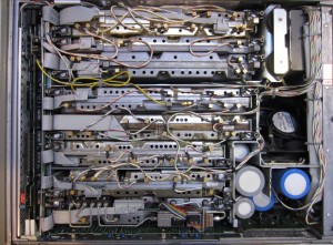
While the goal of this post is not a full teardown (see full teardown pictures here), I did take some pictures along the way and will show them here. HP 8642B is not very easy to service unfortunately. If you take a look at the picture below with the top cover removed, you will see why (by the way, it is not required to remove the top cover in order to change the backlight). In order to achieve the tight specifications, all RF boards are heavily shielded inside the custom-molded metal housings. These thick metal enclosures are the main contributor to the 20+ pounds added weight of the unit. And the higher frequency RF interconnects are made using semi-ridged RF cables. Servicing any part of the unit would most likely involve taking out modules and removing many screws. Fortunately, the PDF service manuals provide detailed instructions on how to service each individual component.
To get to the backlight, we need to open up the front panel. The front panel was designed to swing open after removing 5 mounting screws on the top and bottom frames, which does make servicing the LCD (A1A2) and keyboard (A1) modules somewhat easier.
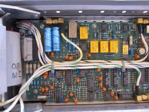
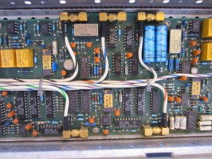
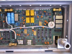
The A1 and A1A2 modules are mounted directly on the front panel. The pictures below shows the A2 modulation module which lies directly behind the keyboard/LCD module when the front panel is closed. The first picture shows the the entire A2 board and the other three pictures are the close-ups.

|
|
|
|
The A1 and A1A2 assembly can be removed after taking out the seven or eight screws that held the board onto the front panel. To remove the board from the chassis, the flat cable on the left (see the first picture above) needs to be disconnected and the cable connecting the rotary encoder on the front panel also needs to be disconnected. Here’s a picture of the A1/A1A2 assembly after being removed from the front panel:
The LCD module (A1A2) can be lifted from the A1 board as it was connected via two headers on each side. The way the LCD module is attached to the A1 board is not the most secure since the distance between the two connectors on the A1A2 module is very long, the LCD module can become detached very easily when A1 is flexed. Fortunately, this is only a problem when servicing as when the modules are mounted on the front panel, all the mounting screws will hold the boards tightly in place. The picture blow shows the reverse side of the LCD module:
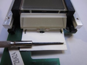
To get to the backlights, the LCD module needs to be dissembled even further. The backlights are housed on each side of the LCD module under a removable cover. after unscrewing the two long screws at the end, the cap can be removed and thus exposing the backlight:
|
|
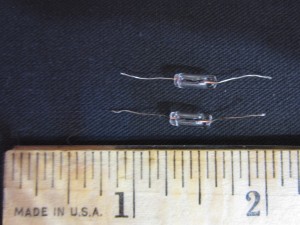
These incandescent lights are very tiny and are soldered directly onto the board. They are spec’d at 5V 115mA and can be turned on and off via special functions 134 and 234. While these miniature incandescent bulbs can still be purchased, I decided to change them to LEDs as these incandescent lights are typically only rated for a life of several hundred hours and it is such a pain to change them.
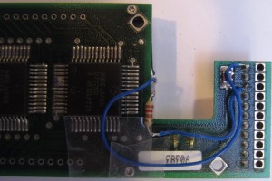
So for this mod, I used a Dremel to sand down a couple of 5mm bright white LEDs so that they can be wedged into the same space where the original bulb sits. The leads were bent right at the base as otherwise they would interfere with the two pushbuttons (LOCAL and MSSG) on each side. A 120Ω current limiting resistor is used to drive each LED, given the 5V supply voltage the current is around 10mA. I could have just soldered the LEDs at the same spot where the incandescent light was placed and use the special function buttons to turn them on and off. But since the display is actually quite hard to see without any backlighting, I decided to make the backlight permanent by soldering the LEDs directly to the 5V supply to the A1A2 board:
The power to the LED on the other side (not shown) is tapped off the 5V supply to the μPD7225 LCD controller. The acrylic light guide underneath the LCD does an excellent job at evening out the light. If you like blue backlight, you can use blue LEDs for this mod. But personally, I think white backlight provides the best contrast for easy reading.
Easter Egg
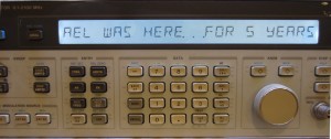
Now, here’s a bit of fun. I am not sure if this is in all versions of the the firmware. At least on mine HP8642B, if you press and hold the MSSG button while powering on, you will be greeted with the following message: “AEL WAS HERE…FOR 5 YEARS”. I am not entirely sure what it was referring to. If you know the origin, please let me know!
