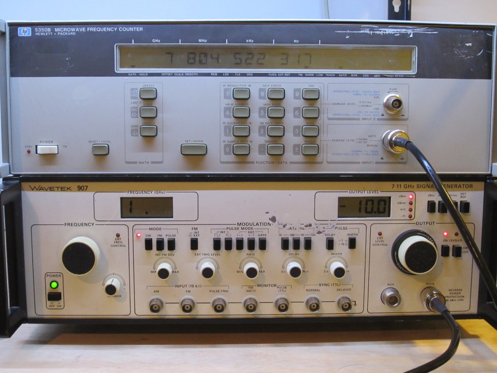
Since I just got myself an HP 5350B microwave counter and I had fixed it up, I thought it would be great if I could get a SHF generator to test out the counter in the microwave range. So when I saw a super cheap Wavetek 907 for sale on eBay, I simply could not pass it up.
This Wavetek 907 is absolutely humongous. It has the same width as my HP 5350B but is much deeper (23 in.) and weights around 50 pounds. It was built in 1980 and is clearly showing its age. It was sold as “used” so presumably it was in working condition. But given the physical condition it was in my expectations were pretty low.
Surprisingly enough though, it did power up and its output signal frequency and range were pretty much spot-on assuming my HP 5350B was accurate. Unfortunately, after I left it on for about an hour to warm up, the frequency display on the Wavetek 907 went over range (displays a “1” regardless of the frequency setting). While it still output a signal, the adjustable frequency range dropped from 6.9 GHz – 11.05 GHz to 6.9 GHz – 7.9 GHz. Also, I noticed that the unit no longer generate much heat and began to cool down. Since Wavetek 907 uses a YIG tuned Gunn oscillator, for the YIG oscillator to function properly the operating environment must be maintained at a relatively high temperature. So given the symptoms, I suspect that the PTC heating element inside the YIG oscillator was probably failing.
At any rate, it is still worth a teardown to see what is inside this signal generator.
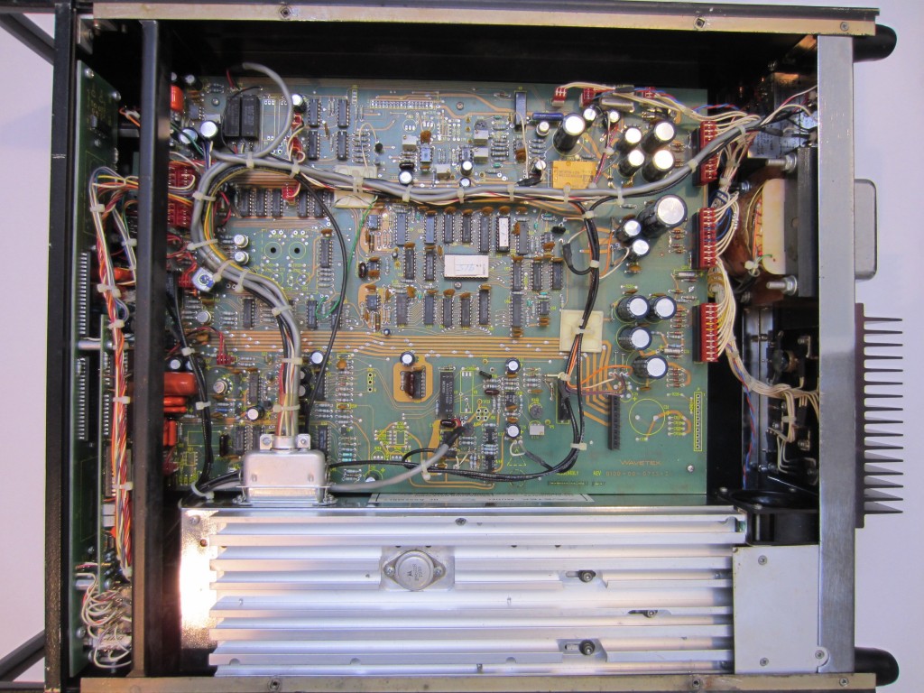
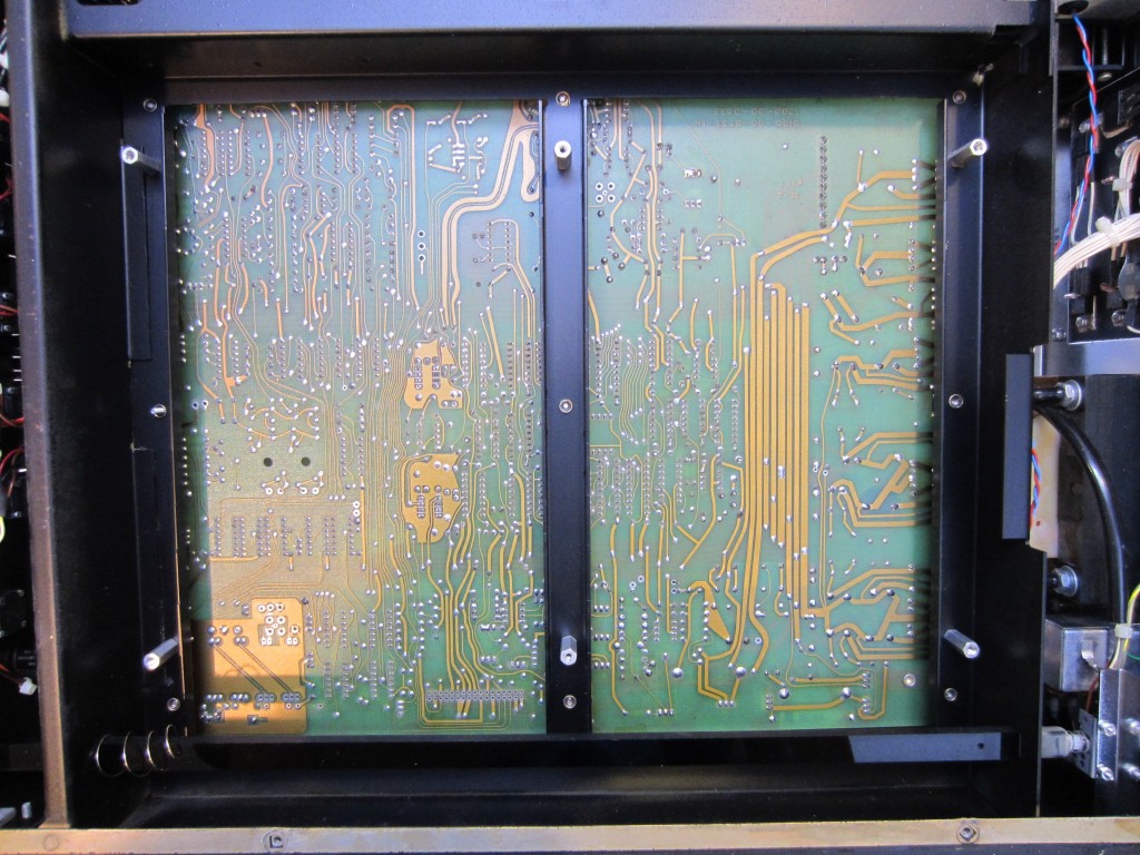
These two pictures below are the top and bottom view of the main PCB (click to see the high resolution version). The date codes on the components also indicate that it was built sometime in 1980. There are some unpopulated foot prints on the board and presumably they are left for options (or could be for the 907A version).
The layout is pretty straight-forward. The big heat-sinked metal can towards the bottom is the RF generator assembly (YIG tuned oscillator). The power supply section is located off the main board on the black heat sink at the rear of the enclosure. From the picture to the right, you can see the push button rod runs from the front panel all the way to the back for the mains switch. This was a very typical construction technique back then so that the high voltage mains wiring could stay in the back and did not have to run all the way across the case.
|
|
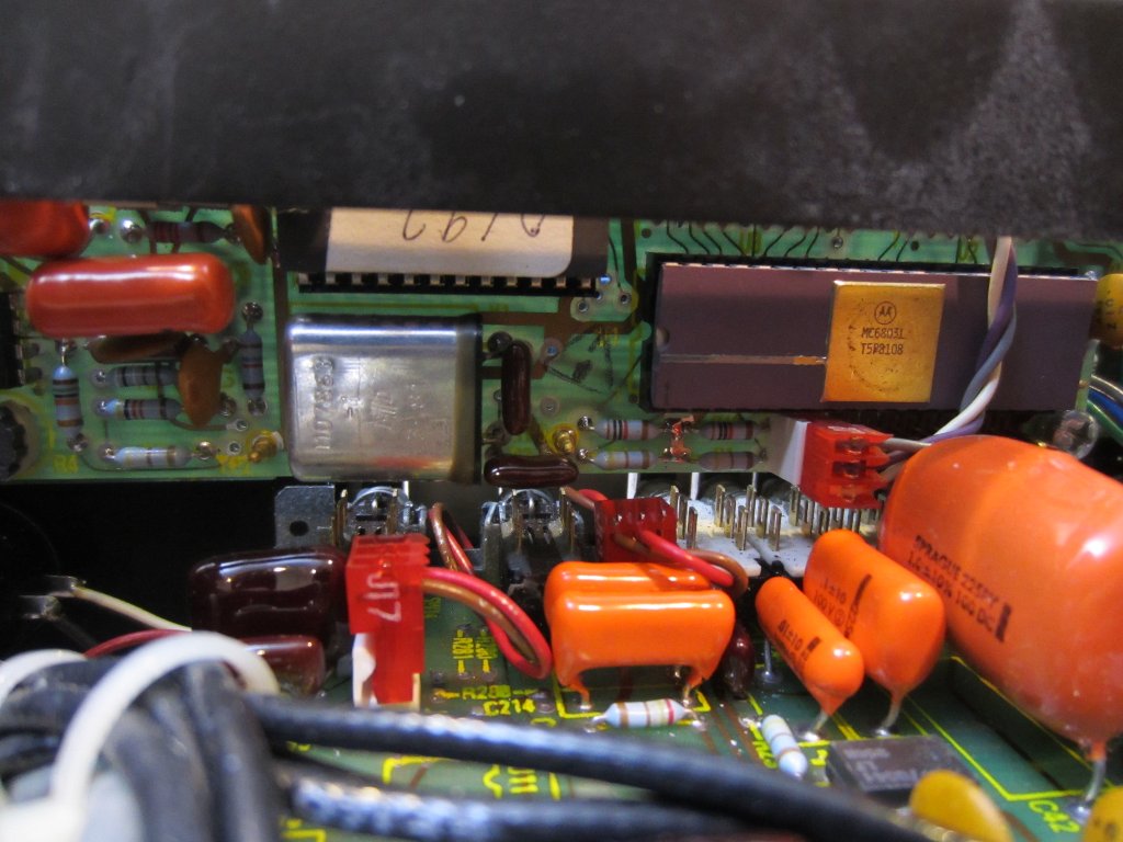
There are two PCBs stack-mounted on the front panel. The larger one mounted next to the front panel is obviously for driving the LCD displays and some other miscellaneous functions. The other one hosts the microprocessor as can be seen in the picture below. The MPU used here is an MC6801.
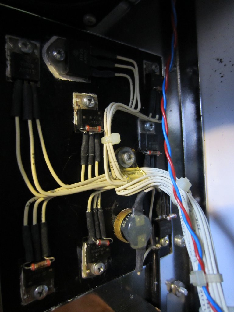
Below is picture of the power supply section (the one on the left). Standard three terminal regulators are used to generate all the required rail voltages and the larger transistor is used to satisfy the higher current demand of the YIG PTC heater. You can also see a thermal switch mounted on the same heatsink towards the bottom. This thermal switch is used to cut off the main power should the power supply become overheated.
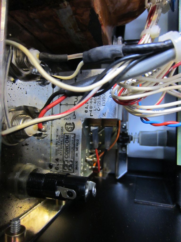
The picture on the right shows the mains filter and a couple rear panel BNC connectors. These BNC connectors are for external frequency control and output level control. In the middle of the picture you can see the mains switch spring-mounted at the end of the push rod that runs the entire depth of the case. Also note the fuse holder at the bottom. This is where the spare fuse is stored and that’s why it is not connected to anywhere.
|
|
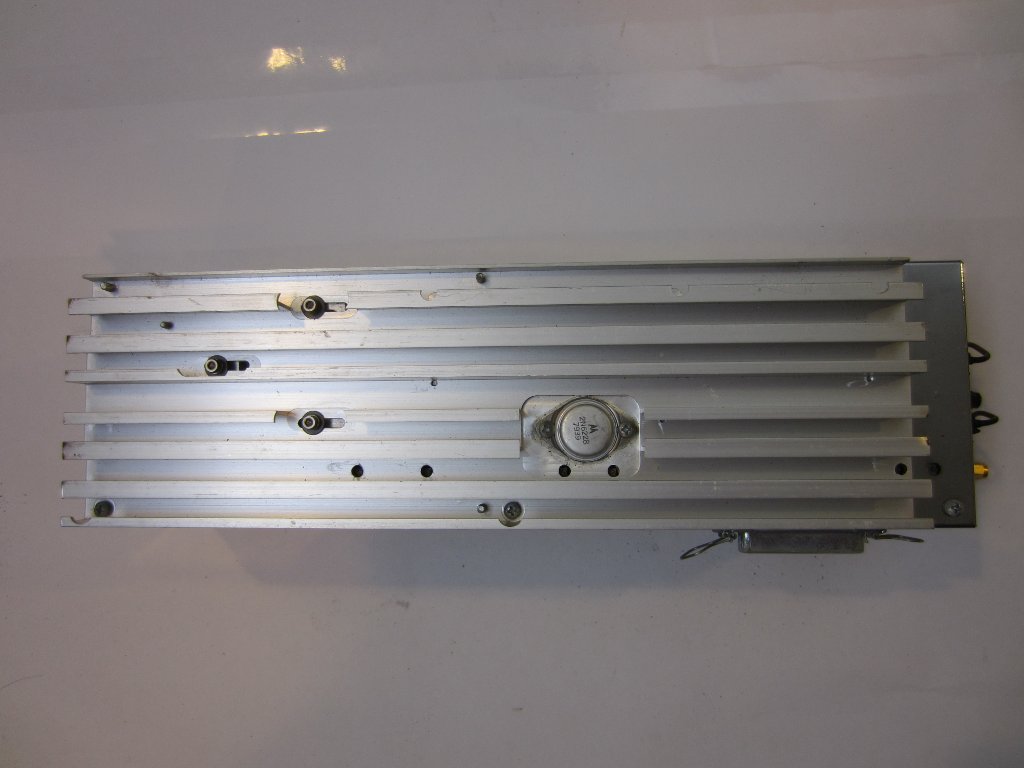
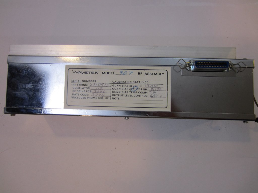
Now it’s time to take apart the RF assembly. The entire assembly can be lifted out of the chassis after loosening the four mount screws at the bottom and removing the two rigid SMA cables. Below are a couple of pictures of the RF assembly removed from the case. Each assembly is manually characterized and the calibration parameters are hand-written on the label outside.
|
|
| [adsense] |
The calibration parameters are different depending on the components used (e.g. different Gunn diode, attenuators, etc.) and that information is captured in ROM when the RF assembly was initially assembled and individually characterized. And that’s why there are two empty IC sockets on the module. Should the oscillator need to be serviced, the ROM chips need to be shipped back so that they can be re-programmed with whatever new values particular to the changed components.
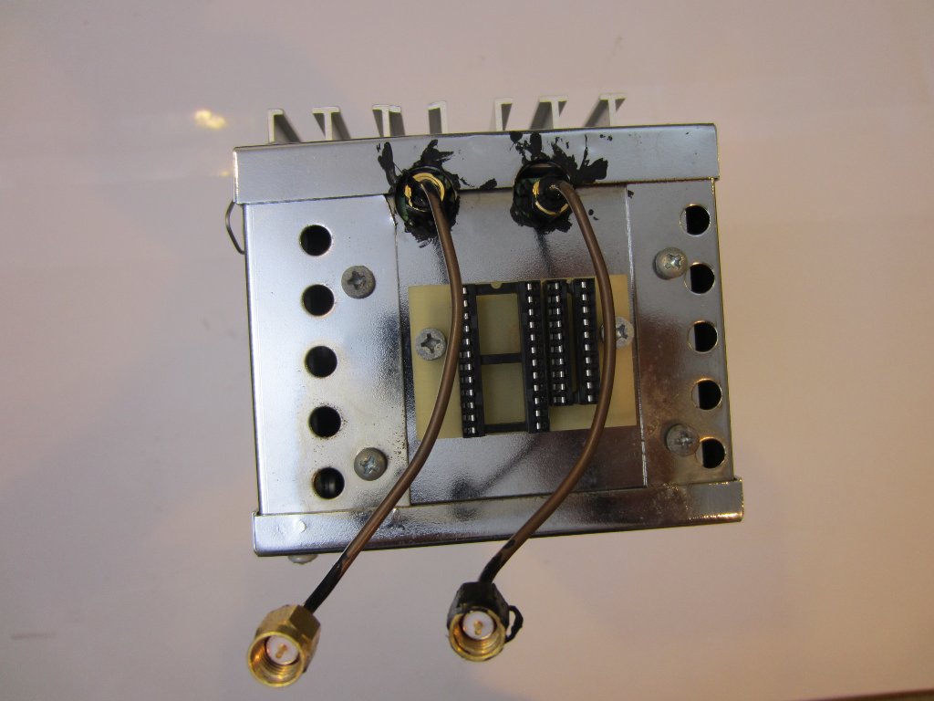
|
|
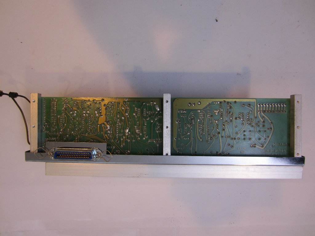
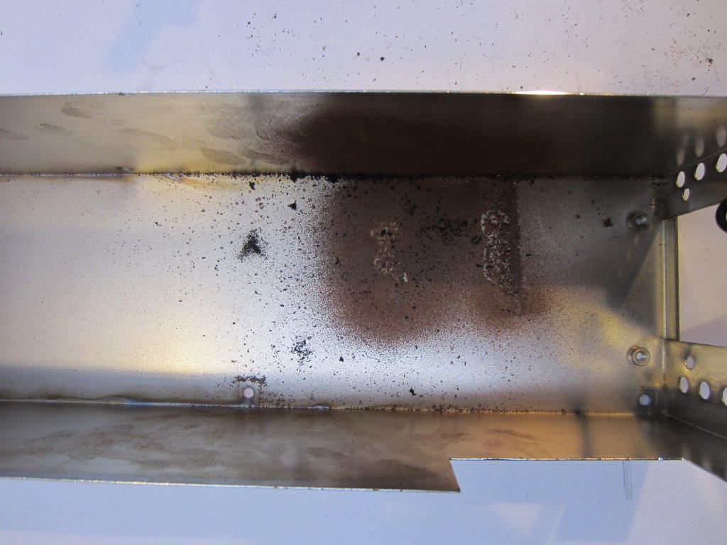
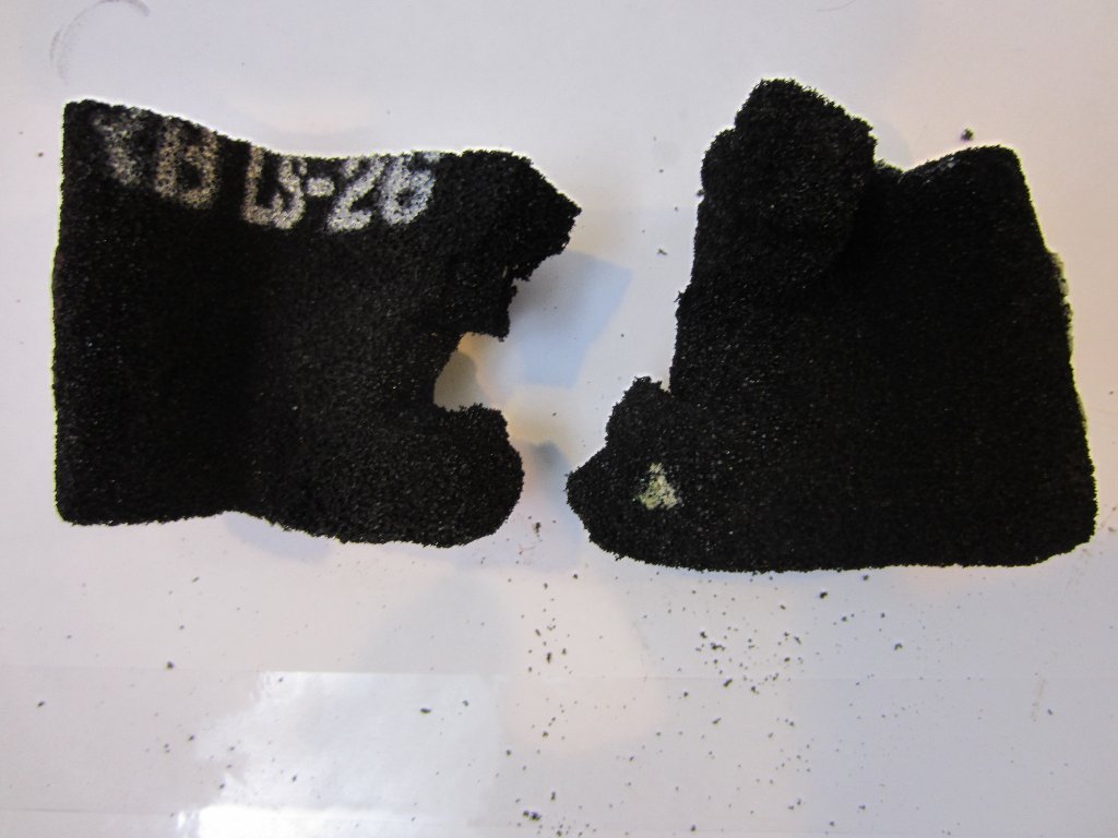
Immediately upon opening the RF assembly, you will notice a large piece of black foam. This foam is so brittle (presumably due to its age) and even a slight touch would reduce portions of it to powder. The foam is marked with LS-26. This is no ordinary foam. For those who are interested, it’s a kind of conductive foam specifically made for microwave absorption. It is carefully placed inside the RF module metal can to absorb any leakage microwave radiation to ensure the output signal’s spectral purity. You can find more details on its product page.
Alas, this piece of foam probably would have cost more than what I paid for the entire signal generator when it was initially made.
|
|
The picture on the left below is what the entire RF module looks like. On the left the large metal cylinder with the heatsink on top is the YIG tuned oscillator. The oscillator output is passed through an isolator (green) and then passed through a chain of electronically controlled RF attenuators (PIN diode levelers) and isolators. The signal is split into two paths, one passes along the leveler chain to produce the main output and the other passes through a simple attenuator to produce the un-leveled auxiliary output.
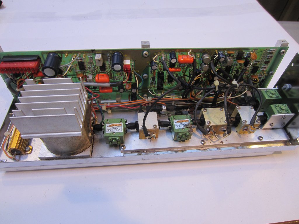
|
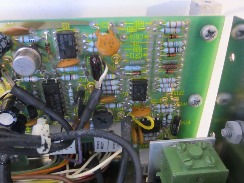
|
Here are a few close-up pictures of the oscillator control circuitry. You can clearly see the coax cables tapped off the circuit board and go into the levelers.
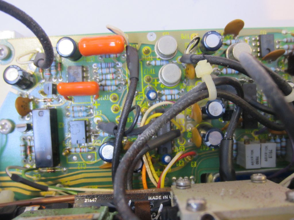
|
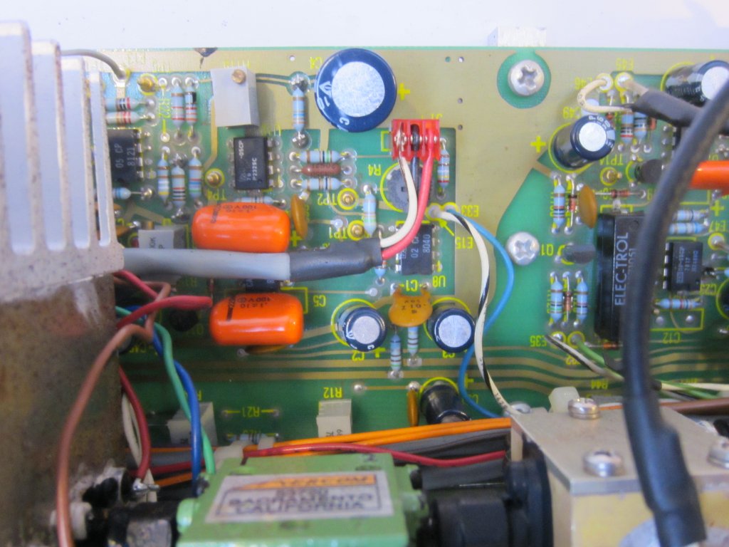
|
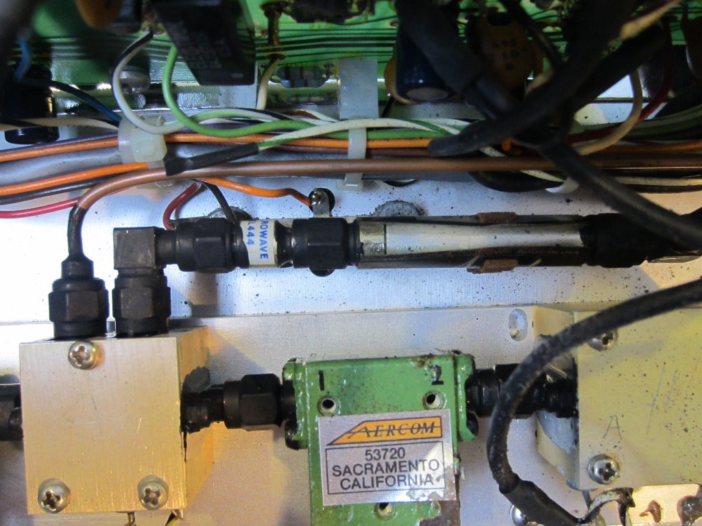
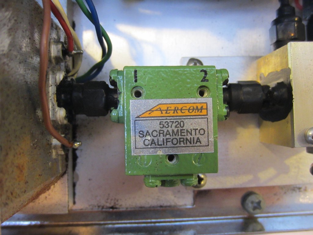
The picture on the left blow shows where the auxiliary output and main output forked off and the picture on the right is a closeup of one of the isolators.
|
|
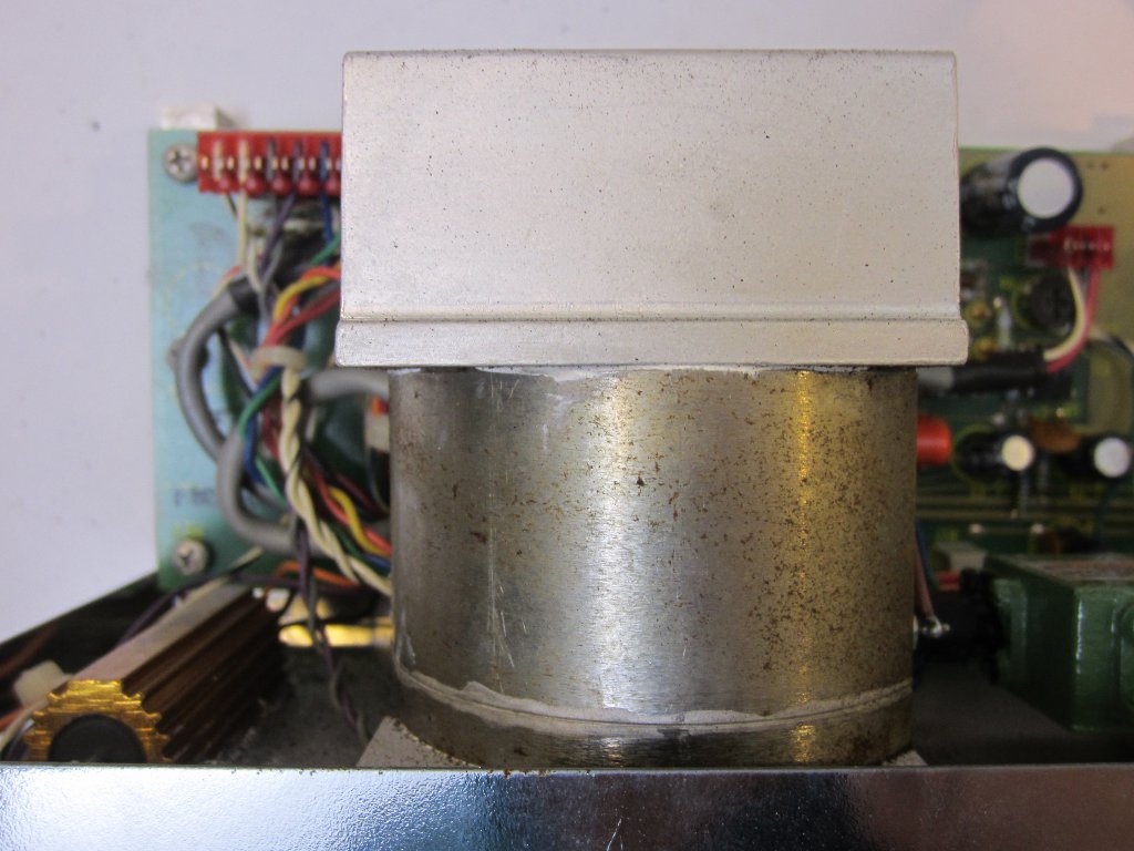
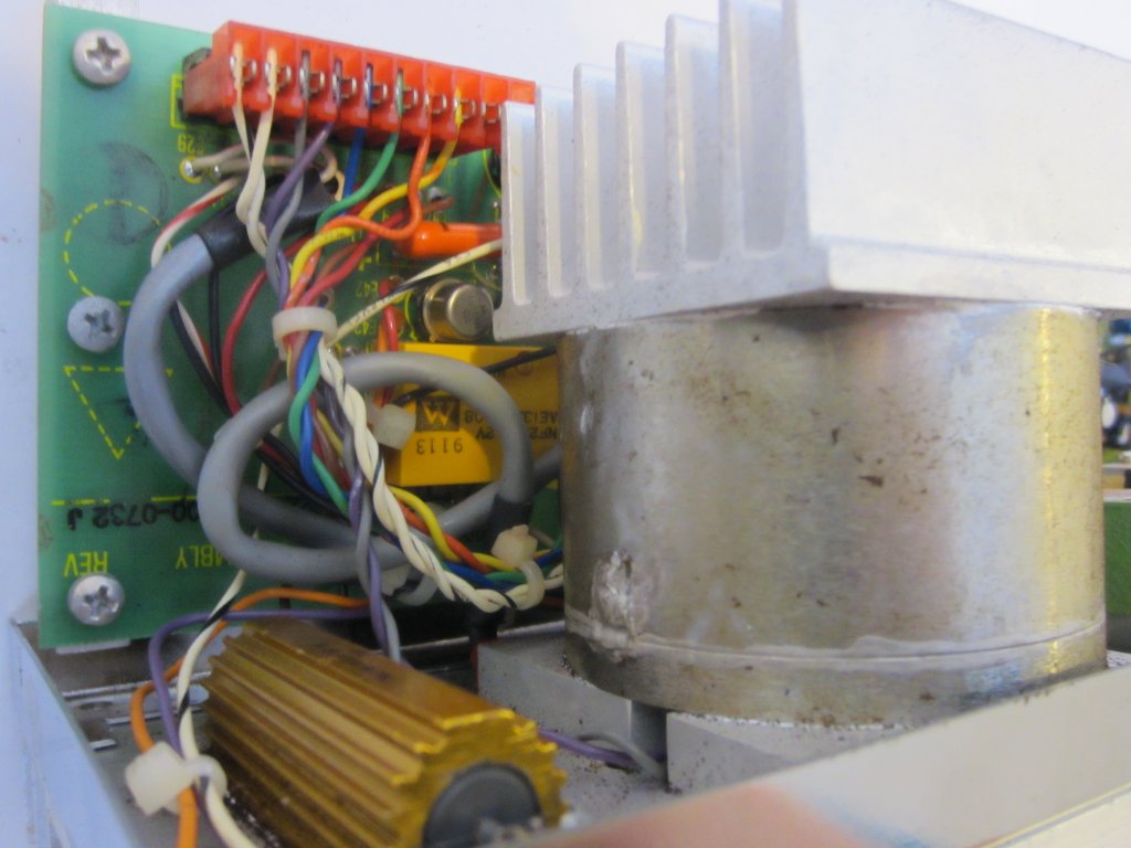
Here are two pictures of the YIG oscillator can. The large 15 Ohm power resistor is the current limiting resistor to the PTC heater of the YIG oscillator. Sadly, the PTC seemed to have failed as the PTC element measures around 240 Ohm under room temperature which is significantly higher than what it should be. This explains why this RF assembly no longer warms up after my initial test.
|
|
Without the heater, the frequency measurement display no longer works as the voltage it references to is way out of range. When I initially powered it on though everything did work but I didn’t take any pictures back then. Anyway, as you can see from the picture below the oscillator still works. It just cannot be adjusted to the wide frequency range that is specified.


