HP 436A is a power meter capable of measuring RF power between -70 dBm and 44 dBm (roughly between 0.1 nW to 25 W) with a frequency range from 100 kHz all the way upwards to 110 GHz depending on the sensor module selected. This power meter was made in the early 70’s and has long been discontinued.
When I saw one at a local auction selling for almost nothing, I could not resist to pick it up. In fact, if you take a look on eBay you will see that HP 436A’s are abundant and most of them can be bought rather inexpensively. But only get one if you really need a RF power meter or you already have a power sensor and cable to go with it as the cable and sensor can easily set you back ten times more than a base unit itself.
If you take a look at the service manual (one of the most complete service manuals can be found here) you will see that HP 436A is nothing more than a precision chopper-stabilized amplifier along with an integrated reference RF signal generator (50 MHz 0 dBm).
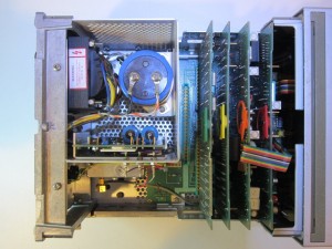
Now let us take a look at what lies inside this ancient power meter. Upon loosening the top instrument cover, you can see a number of vertical boards plugged into the host board mounted at the bottom of the case:
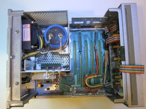
This kind of board-to-board connection design was very popular back then as chip integration level was relatively low and most functionalities were accomplished by the use of daughter boards so that they could be individually serviced and easily swapped out. Here is a picture taken after all the plug-in boards were removed:
The metal can towards the bottom left houses the 50 MHz RF oscillator for the 1 mW reference signal.
Surprisingly, the 50MHz reference signal is not generated by a crystal oscillator, but by a single transistor instead. The output level is precisely controlled via an ALC (Automatic Level Control) circuit. I guess for a RF power meter, the absolute frequency of the reference signal and its stability is not as important as the accuracy of its output power.
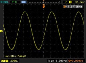
The picture below is an oscilloscope capture of this 50 Mhz 1 mW reference signal.
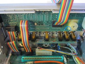
The front panel area as seen in the picture below is mainly occupied by the 7-segment display logic and switch assemblies.
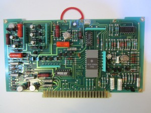
Each of the plugin board has a color coded handle for easy removal. The first one (towards the front of the instrument) is the AC gain assembly (A2 board). The large ROM chip is the range decoder.
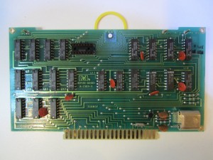
The second board is the A/D converter assembly (A3). The big black module on the right is the auto-zero assembly.
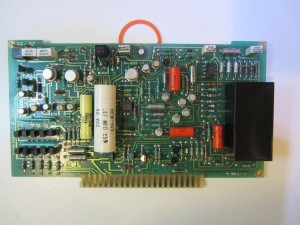
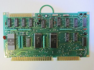
The next board is the counter assembly (A4). This board is clocked at 240 kHz via the crystal oscillator towards the bottom right. Again, the crystal oscillator is based on a single transistor design. Nowadays, crystals are largely driven by TTL/CMOS gates.
The last plugin board is the controller assembly (A5). The two larger chips (U13, U14) in the middle are a multiplexer and a decoder.
For HP 436A, there are also two options available. Option 22 GPIB, Option 24 BCD interface control. These options boards plug into the empty slot.
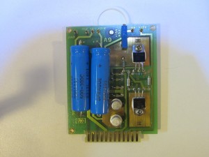
The power supply board is also removable, it provides regulated +15V, -15V and 5V power for the entire unit.
Today, the entire circuitry of HP 436A can probably be handled by a couple of chips.
