I was doing a project that needed a driver for hard disk spindle motors. While I could use a microcontroller to generate the required driving waveform sequence, keeping the waveform in sync with the motor rotation is actually quite tricky especially at higher rotation speeds. To ensure the correct timing sequence, a back-EMF controller is required for these sensorless three-phase BLDC motors.
Back-EMF BLDC drivers can be implemented using microcontrollers as well (Microchip’s AN1083 describes this approach in detail), but there is quite some complexity to it. So I ended up lokking for dedicated three-phase BLDC motor drivers.
After some research, I found two chips that seemed to be able to fulfill my needs. One chip is Taxes Instruments‘ DRV11873, and the other is Microchip‘s MTD6501G. Both chips are very easy to use and are decently priced. TI’s DRV11873 has more features compared to Microchip’s MTG6501G. For example, DRV11873 offers two driving mode (one for high speed motor and one for low speed motor) and has a dedicated pin for setting the rotation direction. The maximum driving current of DRV11873 can be limited via a single external sensing resistor and a dedicated output pin is provided for motor lock-up detection. Motor speed can be adjusted via PWM signal or supply voltage for both chips.
While MTG6501G does not have some of the bells and whistles DRV11873 offers, it does have some advantages. This chip can be used to drive both 3 wire and 4 wire (3 phase with neutral) three phase motors whereas DRV11873 is only suitable for motors with neutral wire. In the case of driving a three phase motor with a neutral lead using MTG6501G, the neutral wire can simply be left unconnected. Also, it requires only a pull up resistor and two bypassing capacitors making it super easy to use.
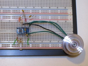
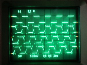
The two pictures below were taken while I was testing DRV11873. The picture to the right shows the driving waveforms. The top waveform is the frequency generator (pin 2) output and the remaining three traces are for the three phases. Note that pin 16 (PWM In) was left unconnected, so the PWM was set at 100% (full power, no modulation).
|
|
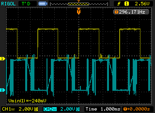
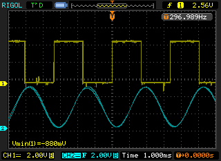
With or without PWM speed control, the driving waveform for each phase is PWM’d sine wave. You can see this in the DSO capture on the left below. The areas around the the sine wave zero-crossing regions are the places where back-EMF is measured. And the image to the right is the filtered (digital low pass filter set to 500Hz) waveform.
|
|
The pictures below were taken while testing MTD6501G. The PWM pin was also left unconnected. The four traces on the oscilloscope are from the frequency generator (pin 1) output and the three phases.
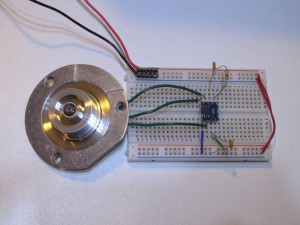
|
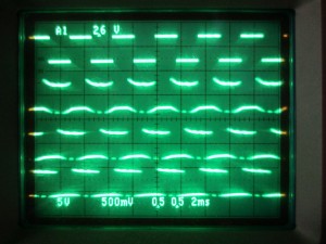
|
Here the waveforms from the frequency generator output and one of the phases are captured using a DSO. The picture on the left shows the PWM sine wave and the the picture to the right shows the filtered (digital low pass filter set to 500Hz) waveform.
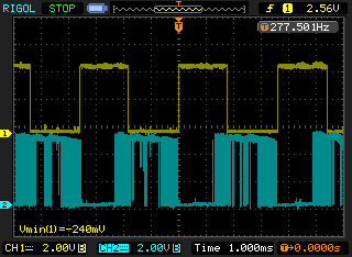
|
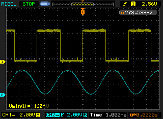
|
Because neither chip is specifically made for driving an HDD motor, the achievable speed range is just around a few thousand RPMs before synchronization is lost (for DRV11873, I did not observe much of a difference with or without the high speed setting).
In my initial testing with RV11873, I did not use a current limit setting resistor and simply shorted pin 14 to ground. It worked fine until I accidentally disconnected the neutral line of motor. The synchronization was lost and the chip was destroyed with magic smoke. So in my subsequent testing, I added back the omitted current limit setting resistor and set the current limit to around 1A. While according to the datasheet the chip could operate without the current limit setting resistor, but I guess it is probably not a good idea.
Anyway for my particular application, either chip would work and could be used without an issue. Both chip performed equally well with the BLDC motors I had. But personally, I am leaning towards MTD6501G as with built-in current limit feature, it is more robust and it requires fewer external components as well.

