Most offline/line interactive UPS‘ (Uninterrupted Power Supply) have a transfer time between 5 to 15 milliseconds. In this post, I will show you the results of the measured switch-over performance of my APC Back-UPS XS1500 and the technique I used.
XS 1500, according to its specifications, switches over to battery power in under 8 milliseconds in the event of a power failure. But what’s the real world performance like? We are about to find out here.
Intuitively, we wanted to observe the time interval between the mains power failure and the time when the UPS output waveform is established. For the most accurate measurement, we wanted to measure the waveform interruption duration at the output side of the UPS as the time interval measured here is what the connected equipment “sees”. So in theory, we should be able to hook up an oscilloscope to the output of the UPS and capture the switch-over event there.
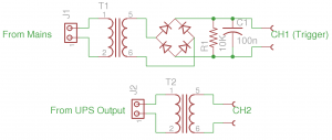
But how do we capture the precise moment of this switch-over event? Without resorting to the internal circuitry of the UPS, we can use the top circuit in the schematics below to achieve this. The transformer used here serves two purposes. First, it provides isolation between the mains circuit and the oscilloscope. This is important as typically both the oscilloscope and the UPS are earth-grounded and accidentally connecting the ground clip to the live line can seriously damage the scope and/or the UPS. Second, lower voltage is much safer to work with regardless of the aforementioned grounding issue.

The lowered AC voltage is then converted to DC voltage via a bridge rectifier. The RC circuit connected after the bridge rectifier is the key here. For the given components values, the RC constant is roughly 1 millisecond. This means that during each cycle, the rectified waveform will not totally drop to zero before the next cycle begins. If we set the oscilloscope to trigger below this “residual” voltage on the falling edge we can capture the mains power event. In practice, the RC value can be chosen anywhere between 1 and 10 milliseconds.
In the bottom half of the schematics above, again a transformer is used for isolation and safety purpose. This transformer is connected to the output of the UPS. In my setup, the trigger waveform is connected to channel one and the UPS output is connected to channel two.
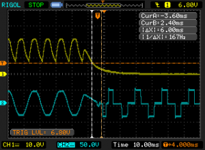
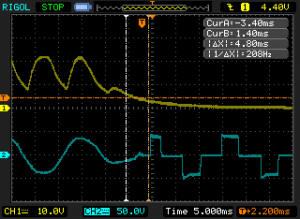
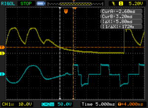
The following three oscilloscope captures are single-shot results from three different runs. In each image, you can clearly see the waveform changes from a sine wave (mains voltage) to a modified sine wave (UPS voltage). The transfer time is measured between the trigger cross-over point (the intersection between the orange trigger level line and the white cursor line) and the first major edge of the UPS output waveform.
As you can see, the measured transfer time is between roughly 5 and 6 millisecond which is well within the specified 8 ms figure.


