I typically use linear regulators (e.g. 7805, LM317, etc.) in my projects. Linear regulators (especially the low dropout ones) are great when the load is light and input/output voltage difference is small, otherwise you will need a big heatsink as significant amount of power is dissipated as heat. The heat issue was evident in my earlier build of the VFD clock. Given how easy it is to use a switching regulator nowadays, there really is no excuse to settle on a linear regulator in situations like this.
TI‘s TPS5420 is a 2A step-down DC/DC regulator. Given its wide input voltage range (5.5 V to 36 V) and relatively high output current capability (2 A), it is a great chip for building either a fixed or a variable power supply. TPS5420’s specifications closely match (in many cases exceed) those of LM317 and can be used in places where its linear cousin is used.
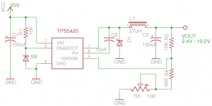
The schematics below shows a simple variable power supply circuit built using TPS5420.

According to the TI‘s datasheet, the circuit’s output voltage is determined by:
\[V_0 = \frac{R3\times1.221}{R_4+R_5} + 1.221 (V) \]
And given the component values I used, the output voltage can be changed between 2.4 V and 19.2 V. The above circuit works the best when the potentiometer used is logarithmic as the potentiometer only changes the denominator value. Of course, it is possible to extend the output range further and improve the adjustment linearity by connecting the wiper to the sense pin (pin 4) instead, but this configuration may cause some instability issues.
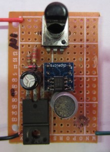
Here is a picture of the variable regulator I built on a proto-board:


