In my previous post, I showed a simple vacuum fluorescent display filament driver built using a 555 timer and a custom hand-wound, center-tapped toroidal pulse transformer. And as promised in my earlier comment, I am going to show you the remainder of the VFD driving circuit here.
As I mentioned before, there are many driver chips (e.g. MAX6921, MAX6931) readily available for interfacing with VFDs. The driver circuit I am showing here is a bit more complex as it uses only the generic 74HC’s and discrete transistors.
The basic technique for driving a multiplexed VFD is very similar to that for driving a 7-segment LED display. The major difference is the voltage requirement for the control gates and segment. For a VFD, the driving voltage is typically between 20V and 30V instead of the TTL or CMOS logic level used for driving 7-segment LED displays. Thus we must employee some kind of voltage shifting circuitry to translate the logic level signal into the voltage required by the VFD.
Here is the schematic of the VFD driver circuit I built:
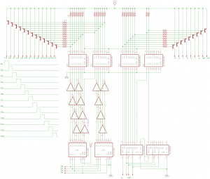
In this schematic, IC5 and IC6 are two 74HC138 3-8 line decoders, they are chained together to generate the strobe signal needed for driving the gate. a couple of 74HC04 inverter chips are used to invert the outputs from 74HC138’s so that the input sequence to the 3-8 line decoders corresponds directly to the grid that is being driven high. Of course, the inverters are not strictly necessary as you could easily invert the control signals in software.
IC7 and IC8 are two 74HC595 shift registers, their outputs are used to drive the nine segments (i.e. a-g, comma and decimal point).
The TTL outputs from IC5-IC8 are translated to higher driving voltages required by the VFD via four ULN2003A darlington driver chips. The output signals from the ULN2003A’s are then inverted by the PNP transistors (all of which are 2N3906). Each PNP transistor controls a control grid or a display segment. Technically speaking, using ULN2003A is a bit of an overkill as the load current is negligible in this case. You could easily achieve the same result by replacing the darlington driver chips with individual NPN transistors such as 2N3904. But using ULN2003A does simplify the circuit a little bit as the base resistors are included on the chip.
Because the current requirement for driving the gates and segments is very low for vacuum fluorescent displays, we can use relatively large load and base resistors. The values of these resistors are not critical and can range from 100K to 1M. Typically, we want to choose larger resistors to limit current consumption. But on the flip side, large resistance value does have some negative impact on signal transition time (e.g. rise time) due to the effect of the large RC constants formed with respect to the BJT junction capacitance. When the refresh rate is relatively low (50Hz to 100Hz), this RC constant has little effect on the quality of the driving signal. But as the refresh rate increases, the RC constant’s effect on the signal slew rate will become more pronounced and causing noticeable ghosting effect. Of course, this issue can be easily addressed by using a complementary output stage, but the resulting circuit will become much more complex and you may as well just use a dedicated driver chip at that point.
Here are a couple of pictures of the driver circuit I built on a perfboard:
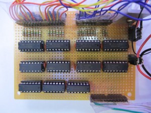 |
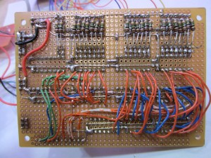 |
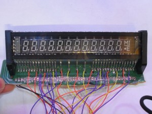
And here is a picture showing the wired-up VFD. The VFD I salvaged was connected to a small PCB. I decided keep part of the PCB and used it as a breakout board for the pins.
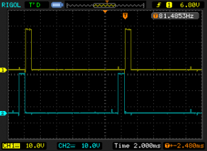
To drive the VFD, a strobe signal (generated via the two 74HC138’s) is needed to assert each of the control grid and while the grid is asserted the corresponding segments to be displayed are driven high. The following oscilloscope capture shows the gate waveforms of two adjacent digits. The gate waveforms are also illustrated in the schematic above. To prevent two adjacent VFD segments being addressed at the same time due to degraded slew rate mentioned earlier, there should be some delays between adjacent pulses. A few microseconds is usually sufficient.
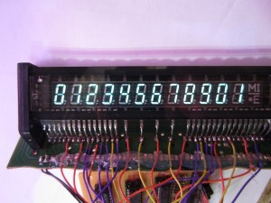
This circuit can be used to interface with a microcontroller directly. To test it out, I used an Arduino to generate the following display sequences (code included at the end). The picture on the left shows what the display looks like without a filter, and the image on the right shows the same display with a blue filter. As you can see even without a filter, the numbers displayed on the VFD are pretty clear:
 |
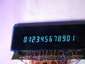 |
Here is the simple test program I used to generate the numbers displayed above. Note that only the first 12 digits are used and the last segment is purposely left blank.
#include <Arduino.h>

const int NUM_OF_GRIDS = 13;
const int PIN_B0 = 2;
const int PIN_B1 = 3;
const int PIN_B2 = 4;
const int PIN_B3 = 5;

const int PIN_DS = 6;
const int PIN_OE = 7;
const int PIN_LATCH = 8;
const int PIN_CLK = 9;

//'0'..'9'
const int DIGITS[]={63, 6, 91, 79, 102, 109, 125, 7, 127, 111, 63};
const int DASH = 64;
const int DOT = 128;
const int COMMA = 256;

int gridCounter = 0;
int b = 1;

void setup()
{
    for (int i = 2; i<=9; i++) pinMode(i, OUTPUT);
}

void loop()
{
    //generate pulse to drive each grid
    digitalWrite(PIN_B0, gridCounter & 1);
    digitalWrite(PIN_B1, (gridCounter & 2) >> 1);
    digitalWrite(PIN_B2, (gridCounter & 4) >> 2);
    digitalWrite(PIN_B3, (gridCounter & 8) >> 3);
    digitalWrite(PIN_OE, LOW);

    if (gridCounter % NUM_OF_GRIDS < 10) {
        b = DIGITS[gridCounter];
    } else {
        if (gridCounter == NUM_OF_GRIDS - 1) {
            b = 0; //skip the last segment
        } else {
            b = DIGITS[gridCounter - 10];
        }
    }

    //displays DIGITS[gridCounter]
    digitalWrite(PIN_LATCH, LOW);
    shiftOut(PIN_DS, PIN_CLK, MSBFIRST, b >> 8);
    shiftOut(PIN_DS, PIN_CLK, MSBFIRST, b);
    digitalWrite(PIN_LATCH, HIGH);
    delayMicroseconds(1000);

    //clears current digit to prevent ghosting
    digitalWrite(PIN_LATCH, LOW);
    shiftOut(PIN_DS, PIN_CLK, MSBFIRST, 0);
    shiftOut(PIN_DS, PIN_CLK, MSBFIRST, 0);
    digitalWrite(PIN_LATCH, HIGH);

    digitalWrite(PIN_OE, HIGH);
    digitalWrite(PIN_B0, LOW);
    digitalWrite(PIN_B1, LOW);
    digitalWrite(PIN_B2, LOW);
    digitalWrite(PIN_B3, LOW);

    gridCounter++;

    if (gridCounter >= NUM_OF_GRIDS) gridCounter = 0;
}

