The current sourcing/sinking capability of the I/O pins on Raspberry Pi is quite limited. According to the Wiki page, the current limit for each I/O block (e.g. GPIO0 through GPIO27 combined) comes at only 26 mA maximum, which is only capable of driving a couple of LEDs at a time. Also the I/O pins are 3.3V only, and going beyond the current or voltage limit could result in permanently damages to the chip.
If we only need to boost the output current, we could use a simple transistor or MOSFET to overcome the current limit. Alternatively, we could use a Darlington array chip such as ULN2003 for the task. ULN2003’s on-state input voltage is well below 3.3V and can be driven directly from Raspberry Pi’s I/O pins conveniently. Keep in mind though, due to the limited current capability of Raspberry Pi the maximum speed at which ULN2003 can be driven is limited due to its relatively large input capacitance and input current requirement. So while ULN2003 can deliver a rather high load current, it is only suitable for interfacing with slower peripherals that operate at a speed no higher than a couple hundred KHz.
What if we need to interface both the input and output with 5V logic? In this case, a bidirectional level-shifter is needed. When speed is not an issue and the load current is low, a simple resistor divider may be used. For high speed applications however, we would need a dedicated level-shifter. Analog Devices’ ADG3300 is designed for this very situation. One of the key benefits of using ADG3300 is that this chip has an internal one-shot generator that ensures fast rising and falling edge of the signal transients and thus can be driven at a speed well into the MHz range. Another benefit of AD3300 is that no directional control pin is needed, the level-shifting happens simultaneously both ways. But ADG3300 cannot be used to drive high current load. In fact it is designed to drive logical gates only, which means that the current delivered is well under a few mA at the best.
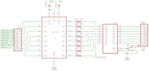
To improve the output current capability, we can interface the ADG3300 with a bus transceiver such as 74HC245. The following schematic shows a bidirectional level-shifting buffer using both ADG3300 and 74HC245:

74HC245’s Vcc (not shown) is tied to Vcc2, and the input/output direction is controlled by the direction pin. In my example, the direction pin is controlled by a switch but it could be controlled via a microcontroller’s output as well. The 1K resistors are added to prevent parasitic oscillation.

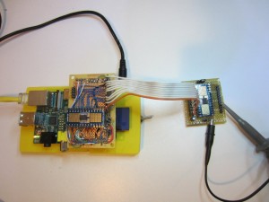
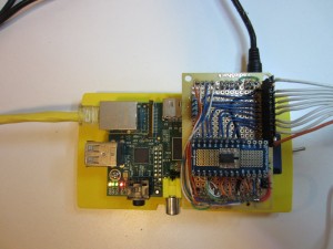
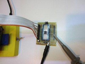
To make it easier for experimentation, I put ADG3300 and 74HC245 on two separate boards and connected them via a ribbon cable. I also included a jumper to switch Vcc2 between 3.3V and 5V so that I could use the same setup for both 3.3V and 5V circuits.
 |
 |
Of course, you could just use a bus transceiver chip such as SN74LVC4245A for both level-shifting and buffering. But for an experimentation platform, the circuit shown above is arguably more versatile.

