I bought a used Topward 6603A lab power supply from eBay a couple of weeks ago and thought I would do a quick review and teardown and perform some basic measurements to see how well it was built.
Topward is a test equipment designer and manufacturer based in Taiwan. According to its website, Topward has been making power supplies since the late 70’s. SpenceTek is the main distributor for the Topward branded instruments here in the United States.
The power supply I got, Topward 6603A, is a dual 60V 3A tracking linear power supply with analog displays. It was made in the late 90’s. There is also a “D” version which comes with 7-segment displays. Judging by the retail price, which is typically in the $700 to $800 range, this power supply clearly is geared towards the professionals rather than the hobbyists. But there are many used ones out there and you can grab one off eBay for only a fraction of that price. Here is a picture of the power supply I received:
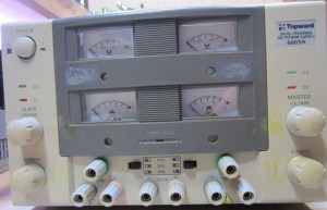
Besides the tape residue on the front panel, there is very little sign of wear and tear elsewhere. This unit appeared to only have been lightly used. Before opening it up, let’s take a look at its specifications (source):
| Output Voltage | 0-60V X2 |
| Output Current | 0-3A X2 |
| Constant Voltage Characteristics | |
| Load Regulation | ±0.01%+2mV |
| Line Regulation | ±0.01%+2mV |
| Ripple & Noise (≤200W): | ≤0.5mVrms |
| Ripple & Noise (>200W) | ≤1mVrms |
| Constant Current Characteristics | |
| Load Regulation (≤200W) | ≤10mA |
| Load Regulation (>200W) | ≤15mA |
| Line Regulation | ±0.01%+2mA |
| Ripple & Noise (≤200W) | ≤1mArms |
| Ripple & Noise (>200W) | ≤3mArms |
| Display Accuracy | |
| Analog Display (A) | Full-scale 3% |
| Digital Display (D) | ≤0.1%+2d |
| Programming Speed | |
| Rise Time (No Load) | ≤100mS |
| Rise Time (Load) | ≤200mS(<6A), ≤500mS(<10A), <1S(≥10A) |
| Fall Time (No Load) | ≤2.5S |
| Fall Time (Load) | ≤250mS |
| Output Impedance | <2mΩ+2µH |
| Recovery Time | ≤100µS to within 0.1% of set voltage (50% to 100% load change) |
| Function | |
| Series Connection | Different models can be connected in series (≤240V) |
| Parallel Connection | Same models can be connected in parallel (≤24A) |
| Power Source | ACV 100/120/220/240±10%, 50/60Hz |
| Tracking Operation | |
| Tracking Error | ±0.2%+10mV |
| Series Regulation | ±0.3%+10mV |
| 5V Fixed Operation | |
| Load Regulation | ≤10mV |
| Line Regulation | ≤0.5mV |
| Ripple & Noise | ≤2mVrms |
| Voltage Accuracy | 5V ±0.25V |
| Output Current | 5A |
| Operation Mode | |
| Independent | Two independent outputs and 5V fixed output; Output from 0 to rating voltage and 0 to rating current |
| Series | Output from 0 to ± rating voltage at rating current; Output from 0 to double rating voltage at rating current |
| Parallel | Output from 0 to double rating current at rating voltage |
Note that this specification listing is a lot more detailed than you would typically find in a power supply that is designed for the hobbyists (e.g. a Mastech power supply), but this is exactly what to be expected for any proper lab equipment.
This power supply is rather heavy (around 30 pounds) due to the large transformer inside to support the rated power dissipation (>400W). And yet it feels very sturdy when being moved around. The top cover of the case can be removed by loosening the four screws on the sides and the two screws on the handle bar. Here is what you see with the cover removed:
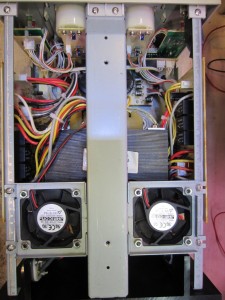
As you can see, there is a support bar in the middle through which the handle bar is attached. And the two bars on either side where the circuit boards are mounted give the structure additional rigidity. The two 60mm Jamicon fans blow air outward. When the top panel is on, it effectively seals off the boarders of the fans and thus allows more efficient air flow for cooling. The fans are rather loud however, and they are constantly on. This can be a bit annoying especially if your lab doesn’t have much ambient noise. I am not sure if Topward had made any revisions to the original design to allow the fans to be thermally controlled. Well, I guess modifying the fan control circuit will be my next project (Adding a Fan Controller to Topward 6603A).
The circuit board for each channel of the power supply is mounted vertically on each side, with the bottom of the PCBs facing outward to ease trouble shooting. Here is a picture of the circuit board on one side:
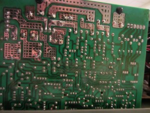
The high current traces are heavily tinned to reduce resistance. These traces employee a grid pattern to provide thermal relief during tinning. Since there is no silk screen on the reverse side of the board, it would be difficult to get measurements if you don’t have a board layout diagram in front of you. But it shouldn’t be a huge problem, as the component density is not that high on these kind of single sided boards.
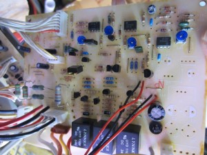
The two regulator boards are mounted onto the top frame using a push-pin mechanism similar to that used on some CPU heatsinks, and the bottom sides are held in grooves at the bottom of the case. Basically, when you push down the pins, the rear end of the pin expands and thus secures the board in place. And when you push the center of the pin from the reverse side, the pin pops out and the board can be removed easily.
 |
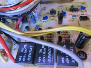 |
As can be seen in the pictures above, the layout of the boards is very clean and the components are mounted neatly. Most of the cable connections are done with connectors, which makes after-market servicing a lot easier. But the fan wires (two pairs of black and red wires on the left) are soldered onto the board directly. In the pictures, you can see that the op-amp used is CA741, which is quite common in linear power supplies. To reduce heat generated via power dissipation, each channel utilizes three relays to switch between the input transformer taps depending on the output voltage. The switching points are roughly at 15V, 30V and 45V when measured at the regulated terminal outputs.
The fixed 5V supply (picture below) is handled on a separate PCB using an LM723 with an external pass transistor.
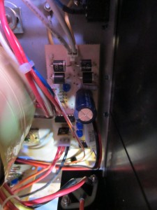
The main rectifier and capacitors are located on yet another separate PCB near the front. The two filter capacitors are marked as 4700uF 100V. One of the things we need to pay special attention to when buying used power supplies is to make sure that the filter capacitors are still in good shape. Typically, these capacitors’ rated MTBF is in the range of thousands of hours, but the operating environment especially the temperature has great impact on the actual lifespan of these components. I measured these two 4700uF capacitors and it seems that they are still within spec.
Towards the bottom left of the picture, you can see a few more relays (four more to be precise). These relays are used to switch the operation mode among independent, series and parallel. This design makes it easier to use the power supply in different modes as you do not need to manually reconfigure the terminals. For most cheap entry level linear power supplies, you will have to connect the two independent terminals together when in parallel mode and connect them in series when in series mode.
For the analog meter model, there is very minimal amount of circuitry on the front panel.
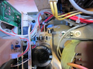
Here is another picture showing the front panel portion of the circuit from a different angle. As you can see, a control circuit board is stacked on the back of the front panel board that contains the mode switches, power terminals and the potentiometers, etc..
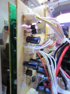
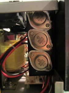
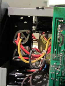
All of the power transistors are mounted on the two “T” shaped heatsinks at the back end of the power supply. These two heatsinks are then mated in the middle, forming a rather large heat dissipating surface. The power transistors used here are 2N3772, which is slightly beefier than the more commonly used
 |
 |
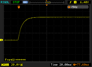
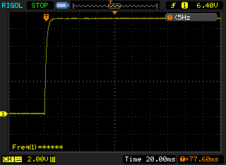
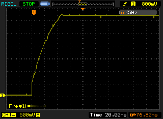
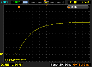
I took a few single shot oscilloscope captures to measure the power-on response. Osc1 shows the power-on voltate characteristics of the master channel with no load when the output voltage was set to the maximum value. The settle time is at around 42ms. Osc2 shows the power-on voltage curve of the same channel set at a lower voltage immediately after Osc1 was taken. Since the main capacitors were remain charged, the settle time was very quick (around 10ms). The third screen capture (Osc3) shows the power-on characteristics when the output voltage was set to 3.3V and a 1.4 Ohm load resistor was attached. Note that the current limit was set to the maximum and the power supply was operating in CV mode. The measured settle time in Osc3 was also around 42ms. The last screen capture (Osc4) shows the power-on characteristics when the power supply was forced into CC mode while the current limit was set to the maximum. The same 1.4 Ohm load resistor was attached. This time it took around 120ms for the voltage to stabilize. Clearly, all these results are well within the specified characteristics and most importantly there was never any observed voltage overshot.
 |
 |
 |
 |
So it appeared to me that overall Topward 6603A is a very well made linear power supply.

