Over the past couple of weeks, I had been busy playing with Microchip‘s MCP2210 USB to SPI converter. I was planning to create a Linux based API since Microchip only provided the Windows version. What I quickly found out though was that the oscillator circuit for MCP2210 was quite finicky, and it took me a while to find an alternative solution.
The 12Mhz oscillator circuitry for MCP2210 is fairly standard, it uses either a crystal oscillator with two load capacitors or a ceramic oscillator. In theory, it should just work. In fact, I had never had any issue with this type of oscillator circuit in the past when building various MCU projects. But after I built the test circuit based on the 5V Vcc reference design in the datasheet using a HC-49 12MHz crystal, I realized that the oscillator did not work. Even though I knew that the capacitors and the crystal I used were not the issue (I had verified that the oscillator worked beforehand), I swapped in a few different ones just in case but still could not get the 12MHz signal on the oscilloscope. One weird thing is that, by holding the circuit in the reset state (e.g. tie the RST pin to ground level) I could see the output waveform from the oscillator. So there is definitely something strange about MCP2210’s internal oscillator circuit.
After some research, I found out that the issue I ran into is apparently a rather common one. I suspect that MCP2210 has some very stringent requirement on the oscillator components and the board layout. It may work on a carefully designed product PCB, but might have issues with the stray capacitance introduced when using a protoboard. Since I am building the circuit on a prototyping board I had to find an alternative way to get the oscillator working.
The Solution
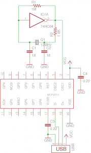
So my solution is to use an external oscillator and inject the clock signal into the OSC1 pin and leaving OSC2 float. This is actually a quite standard design practice as most on-chip oscillators can also be driven externally. You can refer to this design guide to find the proper values for the oscillator components. The following schematic shows the working circuit.


