I got a Syma S107G IR controlled helicopter for my son a while ago. This tiny remote control helicopter is a rather amazing toy. Not only its movement is very stable, but the rotor speed, forward backward movements and turning can be all proportionally controlled as well. I thought it might be interesting to take a look at its control protocol to see how things are done. And yes, I do have a video at the very end showing controlling the S107G using the reverse engineered remote control.
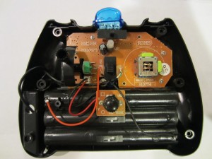
Before I started decoding the IR protocol, I was hoping that I could find some useful information by examining the circuit board of the remote control. So I took it apart:
 |
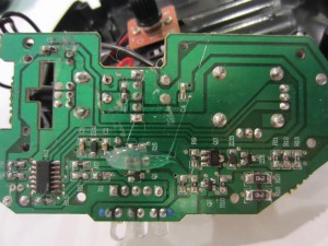 |
Well, it appeared that the transmitter for the S107G uses an MCU to do all the encoding which means that without taking a look at the actual code, there isn’t too much information I could get by just staring at the board. Unfortunately, the marking of the MCU was purposefully sanded off (a rather common practice in the commercial world) so I couldn’t figure out the actual microcontroller used in the circuit easily either.
By looking at the silkscreen though, it seemed that the transmitter works at either 38kHz or 57kHz, which corresponds to either channel A or B that the transmitter can operate on. Another piece of information I gathered is that three potentiometers are used to control the throttle and directions. Presumably, the voltage outputs from these potentiometers are coupled onto the ADC pins of the microcontroller.
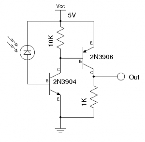
So I decided to dig a little big further by analyzing the actual IR signal. The first step I took was to view the IR signal sent from the transmitter. This can be done in a couple of ways, one way is to measure the waveform directly from the output photo diode on the transmitter and the other way is to use a receiver circuit and measure its signal output. Here, I used the latter method. The following schematic shows the simple IR receiver I made to analyze the signal.
 |
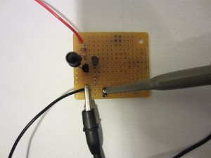 |
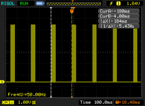
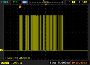
First I wanted to see the modulated IR waveform so I used a standard IR photo diode as the sensor and hooked up the output to an oscilloscope. From the data capture, we can see that the IR command repeats at an interval of 184 milliseconds. Zooming in onto each section we can see the modulated IR signal. The image below on the right shows the modulated waveform of a command, repeating at an interval of 184 milliseconds.
 |
 |
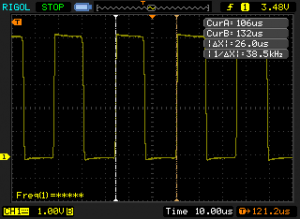
And by zooming in further, we can see that the IR signal is modulated at roughly 38kHz which corresponds to one of the transmitter’s operation modes. The carrier waveform has a duty cycle of roughly 50%.
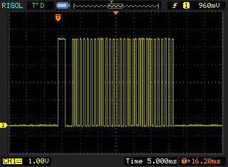
In order to analyze the IR encoding scheme, we will need to use the demodulated waveform. IR demodulation can be done by replacing the IR photo diode I used earlier with an IR sensor as most IR sensors designed for remote controls demodulate the carrier signal automatically.
Here is an output of the demodulated IR command signal:
Since the transmitter’s output waveform would vary depending on the control levers’ positions, I decided to record a few waveforms with different control positions. And by comparing these recorded waveforms, hopefully we can infer how the control positions are encoded.
The following waveforms are recorded using a combination of throttle and direction control lever settings (click to enlarge). To obtain these waveforms, the oscilloscope was set to deep memory mode and the results from each individual run were trimmed so that the beginning of the commands are aligned. Note that the X axis does not represent time, it simply represents the number of pixels in my oscilloscope screen capture.
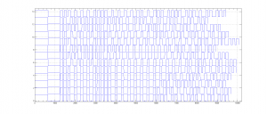
As you can see from the waveform capture above, each signal is consist of 34 pulses. Since for digital systems information is represented in bytes, it is reasonable to assume that the pulses form a 4-byte signal with the extra two pulses as the header. Based on this assumption, the first high-low-high transition marks the beginning of a command. And herein I will refer to it as the header. Since the pulse widths are the same (except for the header), the ones and zeros are distinguished by the duration of the lows. The following graph shows the timing of the signal:

| [adsense] |
So far, we have gathered the following information:
For 38kHz mode:
Command duration:     180  ms
Header High Duration: 2.04 ms
Header Low Duration:  2    us
Pulse width:          380  us
Low duration for 0:   220  us
Low duration for 1:   600  us
For 57kHz mode, everything is the same except the following:
Command duration:     160  ms
Low duration for 1:   660  us
With this information on hand, we can decode each of the IR signals captured above as follows (in the stacked waveform graph above, No. 00 is the one on the bottom):
No. Throttle  Direction                  Binary                              Dec(Hex)
00    ~0%      Middle       00111100 00111111 10001011 00110100    60(3C)  63(3F)  139(8B) 52(34)
01   ~25%      Middle       00111100 00111111 10100111 00110100    60(3C)  63(3F)  167(A7) 52(34)
02   ~50%      Middle       00111100 00111111 11001000 00110100    60(3C)  63(3F)  200(C8) 52(34)
03   ~75%      Middle       00111100 00111111 11100110 00110100    60(3C)  63(3F)  230(E6) 52(34)
04   100%      Middle       00111100 00111111 11111101 00110100    60(3C)  63(3F)  253(FD) 52(34)
05   100%      Left         01101010 00111111 11111101 00110100    106(6A) 63(3F)  253(FD) 52(34)
06   100%      Right        00001000 00111111 11111101 00110100    8(8)    63(3F)  253(FD) 52(34)
07   100%      Forward      01000000 00000001 11111101 00110100    64(40)  1(1)    253(FD) 52(34)
08   100%      Backward     00111100 01111110 11111111 00110100    60(3C)  126(7E) 255(FF) 52(34)
09    ~0%      Left         01101010 00111111 10001101 00110100    106(6A) 63(3F)  141(8D) 52(34)
10    ~0%      Right        00001000 00111111 10001101 00110100    8(8)    63(3F)  141(8D) 52(34)
11    ~0%      Forward      01000000 00000001 10001101 00110100    64(40)  1(1)    141(8D) 52(34)
12    ~0%      Backward     00111100 01111101 10010001 00110100    60(3C)  125(7D) 145(91) 52(34)
From line No. 00 to No. 04, I only changed the throttle position and left the direction control in the middle. From the decoded waveform you can clearly see that the only number that was changing is the third byte and it is apparent that this value is proportional to the rotor speed. Note that throttle value does not start from zero, this is probably mainly for practical reasons as in only higher RPM range could the rotor generate sufficient lift. And by limiting the potentiometer’s output to this range, a finer adjustment in higher RPM range can be obtained.
In line No. 05 and 06, the throttle was placed at 100% and I changed the direction from full left to full right. This resulted a change in the first byte (from 106 to 8). So I inferred that 60 must be corresponding to the center position and the left-right control has roughly 6 bit of resolution from the center.
Line No. 07 and No. 08 are the results from moving the direction lever full forward and full backward while leaving the throttle at 100%. As you can see from the decoded data above, the second byte changed accordingly from 1 to 126. So the forward and backward control is coded in the second byte and it has 7 bit of resolution in each direction.
No. 09 through No. 12 are basically repeating No. 05 to No. 09 except that the throttle was set to 0. Because potentiometers are used for all the controls, the digitized values may be slightly different from the theoretical values even when the controls are set to the same positions each time.
The only byte we have not accounted for so far is the last one. It seems to be fixed at 52 across all the different runs. As it turned out, this byte stores the calibration information and is controlled by the calibration knob on the transmitter. The calibration knob is used to make the helicopter hover without rotating when only the throttle is applied. When the calibration knob is turned right (the helicopter will rotate right when no directional control is applied), this number increases accordingly and when the calibration knob is turned left (the helicopter will rotate left when no directional control is applied), this number will decrease. When trimmed to the appropriate value, the helicopter will be calibrated and will not rotate unless directional control is applied.
So now we have decoded the control scheme. Each IR command is consisted of a header, followed by four bytes which encode the rotational direction (left/right), forward/backward movements, throttle and the calibration data.
To validate the IR control protocol, I wrote a simple program using an Arduino board. The full code listing can be found towards the end of the post. Basically, I used Timer1 to generate the 180ms command repeat interval. Timer2 is used to generate the 38kHz 50% duty cycle PWM carrier signal. Zeros and Ones are generated by turning on and off the 38kHz signal for the desired duration using delayMicroseconds. Three potentiometers were used to control rotor speed (throttle), forward/backward movement and left/right rotations respectively. Since the calibration can be done ahead of time, I chose to hard code the calibrated value in code to simply the control a little bit. Of course, you could always use a fourth potentiometer for this purpose.
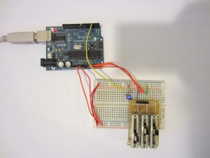
Here is a short video demonstrating the reverse engineered IR control.
|
View on YouTube in a new window |
Conclusion
Reverse engineering is all about methodology, patience and of course lots of luck…
Source code
#include <TimerOne.h>

//comment this out to see the demodulated waveform
//it is useful for debugging purpose.
#define MODULATED 1

const int IR_PIN = 3;
const unsigned long DURATION = 180000l;
const int HEADER_DURATION = 2000;
const int HIGH_DURATION = 380;
const int ZERO_LOW_DURATION = 220;
const int ONE_LOW_DURATION = 600;
const byte ROTATION_STATIONARY = 60;
const byte CAL_BYTE = 52;

int Throttle, LeftRight, FwdBack;

void sendHeader()
{
  #ifndef MODULATED
    digitalWrite(IR_PIN, HIGH);
  #else
    TCCR2A |= _BV(COM2B1);
  #endif

  delayMicroseconds(HEADER_DURATION);

  #ifndef MODULATED
    digitalWrite(IR_PIN, LOW);
  #else
    TCCR2A &= ~_BV(COM2B1);
  #endif

  delayMicroseconds(HEADER_DURATION);

  #ifndef MODULATED
    digitalWrite(IR_PIN, HIGH);
  #else
    TCCR2A |= _BV(COM2B1);
  #endif

  delayMicroseconds(HIGH_DURATION);

  #ifndef MODULATED
    digitalWrite(IR_PIN, LOW);
  #else
    TCCR2A &= ~_BV(COM2B1);
  #endif
}

void sendZero()
{
  delayMicroseconds(ZERO_LOW_DURATION);

  #ifndef MODULATED
    digitalWrite(IR_PIN, HIGH);
  #else
    TCCR2A |= _BV(COM2B1);
  #endif

  delayMicroseconds(HIGH_DURATION);

  #ifndef MODULATED
    digitalWrite(IR_PIN, LOW);
  #else
    TCCR2A &= ~_BV(COM2B1);
  #endif
}

void sendOne()
{
  delayMicroseconds(ONE_LOW_DURATION);

  #ifndef MODULATED
    digitalWrite(IR_PIN, HIGH);
  #else
    TCCR2A |= _BV(COM2B1);
  #endif

  delayMicroseconds(HIGH_DURATION);

  #ifndef MODULATED
    digitalWrite(IR_PIN, LOW);
  #else
    TCCR2A &= ~_BV(COM2B1);
  #endif
}

void sendCommand(int throttle, int leftRight, int forwardBackward)
{
  byte b;

  sendHeader();

  for (int i = 7; i >=0; i--)
  {
    b = ((ROTATION_STATIONARY + leftRight) & (1 << i)) >> i;
    if (b > 0) sendOne(); else sendZero();
  }

  for (int i = 7; i >=0; i--)
  {
    b = ((63 + forwardBackward) & (1 << i)) >> i;
    if (b > 0) sendOne(); else sendZero();
  }

  for (int i = 7; i >=0; i--)
  {
    b = (throttle & (1 << i)) >> i;
    if (b > 0) sendOne(); else sendZero();
  }

  for (int i = 7; i >=0; i--)
  {
    b = (CAL_BYTE & (1 << i)) >> i;
    if (b > 0) sendOne(); else sendZero();
  }
}

void setup()
{
  pinMode(IR_PIN, OUTPUT);
  digitalWrite(IR_PIN, LOW);

  //setup interrupt interval: 180ms
  Timer1.initialize(DURATION);
  Timer1.attachInterrupt(timerISR);

  //setup PWM: f=38Khz PWM=0.5
  byte v = 8000 / 38;
  TCCR2A = _BV(WGM20);
  TCCR2B = _BV(WGM22) | _BV(CS20);
  OCR2A = v;
  OCR2B = v / 2;
}

void loop()
{

}

void timerISR()
{
  //read control values from potentiometers
  Throttle = analogRead(0);
  LeftRight = analogRead(1);
  FwdBack = analogRead(2);

  Throttle = Throttle / 4; //convert to 0 to 255
  LeftRight = LeftRight / 8 - 64; //convert to -64 to 63
  FwdBack = FwdBack / 4 - 128; //convert to -128 to 127

  sendCommand(Throttle, LeftRight, FwdBack);
}

