I was experimenting with I2C using my TI MSP-EXP430G2 Launchpad and ran into some issues. For a while, I could not get the I2C host and slave to talk. After having verified the coding and the hardware setup, my suspicion turned to the jumper which connects the red LED indicator to port pin P1.6.
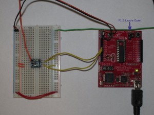
And sure enough, after disconnecting the P1.6 jumper everything worked as expected (the picture below shows an LTC6904 connected to an MSP430G2231) with the P1.6 jumper removed:

The issue is actually quite obvious in hind sight: since P1.6 is the serial clock pin in I2C mode the additional LED indicator may have caused the logic level on that pin to shift due to the extra load placed on it. When the clock pin is driven high, the LED would begin to conduct and drag the line voltage back down (this was later confirmed using an oscilloscope and the logic HIGH was less than 2V when the LED was connected). Thus the I2C master was not able to read from the SDA line due to this irregularity of the clock signal.
So, a simple fix to this problem is to disconnect the P1.6 jumper when using the I2C mode.
Since we can use the internal pullup resistors in MSP430, no external pullup resistors are needed in this single master/slave implementation. In my next post, I will show a couple of coding examples on interfacing I2C devices with the MSP430 Launchpad.

