Last year, I wrote about a simple digital metronome project. While the device worked pretty well there are a few changes that are to be desired.
First of all, I used 16 LEDs as the tempo indicators. These LEDs are lit one by one as the tempo changes. This approach serves the purpose but limits the total number of tempos that can be used. In the original design, I multiplexed each LED with two tempo settings and thus 32 discrete tempos could be displayed. While in theory it is possible to have one LED represent more than two tempo settings and thus provide even more choices, the interface will nevertheless become more confusing.
Secondly, I used simple delay statements in the code to come up with the correct timing. The issue is that the delay function is blocking and thus the mode changing would become a bit sluggish when the tempo setting is low since during the delay no other interactions can be processed.
And finally the output volume was a little bit low due to the use of a simple one transistor output amplifier. In this revised version of the build, I am going to address all these three shortcomings.
The first issue can be easily addressed by switching to an LCD or 7 segment display. Since the tempo settings are three digits maximum and we rarely need tempo settings above 200, I used a two digit 7 segment display to show the current tempo settings. An additional LED is lit when the tempo setting reaches above 100.
The following schematics shows the design:
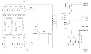
Note that the 7 segment display I used multiplexes the two digits (i.e. only one digit is lit at any given time). This feature helped simplify the circuit design a little bit since only one shift register is needed to drive both digits. Of course, the coding becomes a bit more complex which we will discuss later.
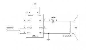
To solve the output volume issue, a better amplifier stage is needed. Since the output signal is already at TTL level, we do not need an amplifier in the traditional sense. All we need is a current buffer so that the output impedance would be low enough to drive the speaker. While this can be achieved by using a single transistor, the output efficiency can be further increased by using a properly designed buffer (e.g. with a complementary output stage). The following schematic shows a simple buffer implementation using the popular 555 timer. In this circuit, the 555 timer is configured as an inverting Schmitt trigger. This circuit can handle an output current of close to 200 mA which is ideal for driving a 16 Ohm speaker.
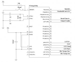
The MCU portion of the circuit is fairly standard. Note that the chip pinouts and the Arduino pin number definitions are different.
Now, let’s take a look at the implementation of the code (the full code listing can be downloaded towards the end). The code was developed using the Netbeans plugin I created earlier. But you can compile the same code using the standard Arduino IDE as well.
There are two methods we could use to eliminate the delay statements in code. One way is to employee an interrupt routine that would interrupt at the time interval according to the tempo setting. Another way is to use a method similar to that used in dead reckoning so that we can keep track of the current time in relation to previously recorded event timestamps. In my implementation, the latter approach was used as it gives slightly more flexibility.
There are four events we need to keep track of: Key debouncing interval, tempo, key press repeat interval and beat duration. The following code snippet shows the implementation of the main loop:
void loop() {
    //determines which 7seg digit to update, each loop updates one of the two
    //7seg displays.
    currentDigit = currentDigit == 0 ? 1 : 0;

    //the MSB determines which 7seg digit is displayed.
    dispDigit = currentDigit << 7 | currentDisp[currentDigit];

    buttonPressed = checkButtonStates();

    //the repeat counter is used to determine how long does it take to repeat the
    //key pressed action when a key is pressed.
    repeatCounter++;

    //if key is pressed and we are at the desired repeat interval
    if ((repeatCounter % repeatInterval == 0) && (buttonPressed == 0)) {
        if (lastBtnStates[BTN_TEMPO_DEC] == LOW) { //tempo down
            if (TempoIndex > 0) TempoIndex--;
        } else if (lastBtnStates[BTN_TEMPO_INC] == 0) { //tempo up
            if (TempoIndex < TEMPO_DISPLAY_RANGE) TempoIndex++;
        }

        currentTempo = TEMPO[TempoIndex]; //records the selected tempo

        if (currentTempo > 0) {
            noTone(PIN_SPK);
            digitalWrite(PIN_LED_GREEN, HIGH);

            //calculate tempo duration in microseconds
            tempoInterval = 60000000l / currentTempo;

            //currentTempo = currentTempo2 * 100 + currentTemo1 * 10 + currentTempo0
            currentTempo2 = currentTempo / 100;

            //tempo above 100 is indicated by lighting the LED on PIN_DIG_LED pin.
            if (currentTempo2 > 0) {
                digitalWrite(PIN_DIG_LED, HIGH);
                currentTempo -= 100;
            } else {
                digitalWrite(PIN_DIG_LED, LOW);
            }

            currentTempo1 = currentTempo / 10;
            currentDisp[0] = DIGIT[currentTempo1];

            if (currentTempo1 > 0) currentTempo0 = currentTempo - 10 * currentTempo1;
            else currentTempo0 = currentTempo1;

            currentDisp[1] = DIGIT[currentTempo0];

            lastBeatTimeStamp = micros();
            beatDurationCount = 0;
        } else {// if the selected tempo is 0, we are in calibration mode
            digitalWrite(PIN_LED_GREEN, LOW);
            currentDisp[0] = DASH;
            currentDisp[1] = DASH;
            tone(PIN_SPK, A_FREQ);
        }
    }

    if (currentTempo > 0) {
        beatDurationCount++;

        // if the beat interval passed, we initiate a new beat
        if (micros() - lastBeatTimeStamp >= tempoInterval) {
            lastBeatTimeStamp = micros();
            beatDurationCount = 0;

            //the beat (LED and speaker) is on only when the beat duration has not passed
            //the beat duration is less then the beat interval
            if ((beatDurationCount < beatDuration) && (!signalLedOn)) {
                digitalWrite(PIN_LED_RED, LOW);
                tone(PIN_SPK, TEMPO_FREQ);
                signalLedOn = true;
            }
        } else { //if the beat interval passed, we turn off the speaker and dim the LED.
            if (beatDurationCount > beatDuration) {
                digitalWrite(PIN_LED_RED, HIGH);
                signalLedOn = false;
                noTone(PIN_SPK);
                beatDurationCount = 0;
            }
        }
    }

    //output a single digit (determined by the MSB in dispDigit)
    digitalWrite(PIN_LATCH, LOW);
    shiftOut(PIN_DS, PIN_CLK, MSBFIRST, dispDigit);
    digitalWrite(PIN_LATCH, HIGH);
}
Because the dual 7-segment display I used is duplexed, additional code was added so that the two digits are updated alternately during each loop. Because the loop executes relatively fast, you will not notice any flickering. In my implementation, the MSB from the output of the shift register is used as an indicator signalling which 7 segment display is currently being updated. As you can see from the circuit design above, each of the 7 segment digit is switched via a PNP transistor.
Since code execution takes time, the actual beat interval may be a few microseconds off the calculated value. But this causes only less than 1% of timing inaccuracy at the highest tempo setting and can be safely ignored.
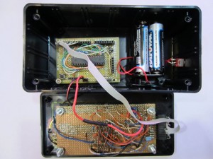
Finally, here is a picture of the finished circuit built on a protoboard. The displays and ICs are mounted on the other side of the PCB.
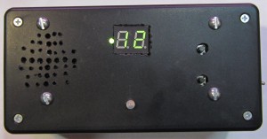
And here is a picture of the metronome in action. As I mentioned earlier, since the leading digit is either 0 or 1 (tempos above 200 are rarely used), I used a LED instead of another 7 segment display for the digit.
Download: MetronomeV1.tar.gz

