In my previous post, I explained the theory behind the self-balancing robot at a high level. Here, I will discuss the actual build in more details.
The following schematics show the circuits for the accelerometer and the gyroscope (the IMU) portions. The choice of the accelerometer and gyroscope is not that critical and they can be substituted with pretty much any other comparable parts that you have. If you do not want to build the IMU yourself, you can always use a pre-built IMU with at least 3DOFs (such as this 6DOF board from Sparkfun). Since low cost is one of my primary objective, I chose to build myself.
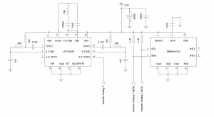
I used a LPY450AL for the gyroscope and anMMA8453Q for the accelerometer. These two devices are rather inexpensive and the IMU can be built for well under $10.
The actual circuits I used are taken directly from the reference designs. For this application, since I am only using one axis from the gyroscope and two axes from the accelerometer, the circuitry for the unused axes not strictly required.
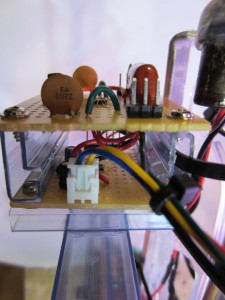
Here are a couple of pictures of the finished IMU boards. I used two small protoboards, one for the accelerometer and the other for the gyroscope. They are stacked together using sections of anti-static IC tubes.
 |
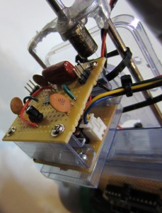 |
Depending on how you are placing the accelerometer and the gyroscope chips in your design, the axes you use will differ. Both of my accelerometer and gyroscope are mounted upside down using the soldering technique I have been using for prototyping. So given this chip arrangement, the y and z axes of the accelerometer and the x axis of the gyroscope are used (more on this next time when discussing the code).
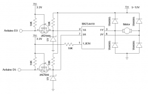
I used an SN754410 for the H-Bridge. Since the logical power supply voltage has to be greater than 4.5V according to the datasheet, the MCU control voltage output range needs to match this requirement.
There are a couple of ways to achieve this. Since the accelerometer and the gyroscope both operate under 3.3V, we could either run the MCU (in this case an ATmega328P) under 5V and use voltage level shifters between the SCL and SDA lines for the I2C interface or run ATmega328P under 3.3V and use level shifters to interface the motor controller.
Either way would work, but I prefer the latter approach for the following reasons:
- The I2C interface operates at a far higher frequency then the motor controller does and thus has much stricter timing requirements on the level shifter. So by placing the level shifters on the motor controller side, we can use simple MOSFET level shifters without having to worry too much about the waveform rising speed.
- Since the gyroscope output is analog, the output voltage is limited to Vcc (3.3V in this case) and thus having the MCU running on the same voltage simplifies the ADC scaling. We do not have to sacrifice the precision or worry about using an external voltage reference.
- Another benefit of using 3.3V for the MCU circuits is that the supply voltage from the battery pack can be further regulated and filtered before supplying to the MCU circuits. This additional filtering provides better isolation from the noisy driving circuit.
When the above circuit is used to bridge between 3.3V and 5V, the zener diode connected to the drain of the MOSFET is not necessary. But if the main supply voltage is higher than 5V, zener diode will be required to clamp the interface voltage so that it will not exceed the maximum allowed logic input voltage of SN754410.
The MCU portion of the circuit is pretty standard. Since the Vcc (3.3V) is very close to the brown-out reset voltage if you are using the default Arduino bootloader settings, I would recommend resetting the brown-out detection fuse bits to prevent the circuits from unexpected automatic reset due to the voltage drop from the high in-rush current of the motor.
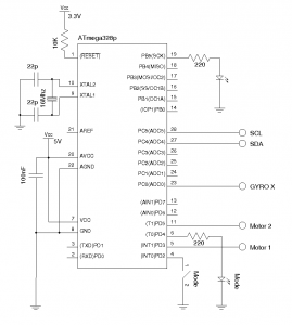
From the circuit above, you can see that I added a few extra components. A mode switch is added to turn on and off the drive train during testing. I have also included a mode LED indicator which is used to provide some feedback on the calibration process.
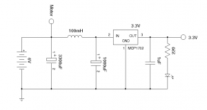
The following diagram shows the power supply portion of the circuit. The H-Bridge is driven directly from the batteries and the 3.3V is provided via an MCP1702 regulator. The LC low-pass filter is necessary to reduce the electrical noise from the motor circuitry since the battery power is shared between the MCU and the motor.
The finished controller board looks like below:
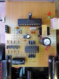
If you look carefully, the above layout differs slightly from the circuit diagrams listed earlier. The main difference is that I implemented all four half bridges on the SN754410 since the motor draws around 0.3A when running but the stalled current rises to around 1A. While the current draw is still within specification, the SN754410 becomes quite warm during normal operations so I paralleled the four half bridges into a single full bridge. Depending on the motor you use, this may or may not be necessary. I also added a serial interface header and an MCU reset button so I could debug and program the MCU more easily without having to remove the chip from the board.
As mentioned previously, I used the drive train from a toy truck as the basis for my build. Generally speaking, in order for the balancing robot to work well you will need to consider the following requirements:
- The motor must be able to accelerate the robot faster than it can fall so that the robot can remain balanced. In general, the faster the motor can move the robot, the larger the inclination angle it can handle in an off-balance situation. Most of the toy trucks with gear boxes should be able to handle this requirement.
- Another requirement is that the maximum vehicle speed — which is independent of the acceleration — should also be adequate for the balancing maneuver. While acceleration is the most important factor when the deviation from equilibrium is small, faster speed is needed to correct larger position errors. It is possible to build a stable balancing robot with a high-torque but low speed drive train, but it would put more demand on the control algorithm and it is generally harder to tune. So the rule of thumb is to get a toy truck that has a powerful enough motor that can accelerate fast and can go at a relatively high speed.
- The backlash of the gearbox also affects the balancing performance. To achieve high stability, gearboxes with small backlash should be used. Unfortunately, most gearboxes in toys have significant backlash and this has a detrimental effect on stability. But you can still built a reasonably good balancing robot with a toy gearbox, it just means that the final robot will be a little bit wobbly.
- The wheels used must have enough traction otherwise they may spin in place without actually moving the robot. So rubberized wheels are preferred.
The toy truck I used for this project has a single motor that drives both of the rear wheels. Since I only need the drive wheels, I cut off the unused front portion. The toy car’s plastic chassis is not rigid enough so I hot-glued a few pieces of plastic and metal support on the back. The extra support is important as excessive vibrations affect the accuracy of the sensor measurements.
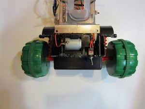
Here is a picture of the finished robot:
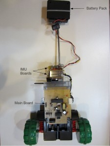
I used a rod to extend the height of the robot to roughly 16 inches and placed the battery pack (4 AA) on the top to increase stability.
Next time I will go over the code, discuss the tuning and show you the self-balancing robot in action. Stay tuned!

