MMA8453Q is a rather inexpensive accelerometer. It is significantly cheaper than many other 3-axis accelerometers (such as the popular LIS3LV02DL) and yet it offers a reasonably high 10 bits resolution and packs a rich set of features that simplifies designs and programming in many different applications.
In this post, I will show you how to interface it with an ATmega328 MCU using Arduino libraries. Because the operating voltage range for MMA8453Q is between 1.95V and 3.6V, you will need to either power your MCU using 3.3V or use an I2C voltage level translator (such as TI’s PCA9517 Level-Translating I2C Bus Repeater) so that MMA8453Q can be powered within its specified voltage range.
MMA8453Q uses the I2C protocol, so I assumed that I could use the default Arduino Wire library. Unfortunately, MMA8453Q uses repeated start condition for the read operations and the default Wire library cannot handle without any modifications. As a result of this, it does not matter which register you try to read from, the returned value is always the content of the status register (at address 0x00) when using the Wire library due to the reset between the write of the register address and the subsequent read. Fortunately, there are alternative I2C libraries available for Arduino that address this issue. And the I2C library I used below is from DSSCircuits.
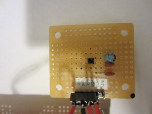
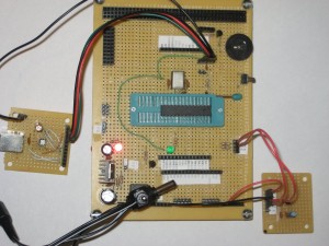
I mounted my MMA8453Q on a proto-board using my favorite hand-soldering method. And connected it to my customized Arduino experiment board and set the board voltage to 3.3V instead of the usual 5V.


The following is some sample code. Note that I only provided a few basic functions and not all the register constants are used in the code. But all the remaining functions can be easily implemented using regRead/regWrite functions and the register definitions listed below:
#include <I2C.h>
const byte REG_STATUS = 0x00; //(R) Real time status
const byte REG_OUT_X_MSB = 0x01; //(R) [7:0] are 8 MSBs of 10-bit sample
const byte REG_OUT_X_LSB = 0x02; //(R) [7:6] are 2 LSBs of 10-bit sample
const byte REG_OUT_Y_MSB = 0x03; //(R) [7:0] are 8 MSBs of 10-bit sample
const byte REG_OUT_Y_LSB = 0x04; //(R) [7:6] are 2 LSBs of 10-bit sample
const byte REG_OUT_Z_MSB = 0x05; //(R) [7:0] are 8 MSBs of 10-bit sample
const byte REG_OUT_Z_LSB = 0x06; //(R) [7:6] are 2 LSBs of 10-bit sample
const byte REG_SYSMOD = 0x0b; //(R) Current system mode
const byte REG_INT_SOURCE = 0x0c; //(R) Interrupt status
const byte REG_WHO_AM_I = 0x0d; //(R) Device ID (0x3A)
const byte REG_XYZ_DATA_CFG = 0xe; //(R/W) Dynamic range settings
const byte REG_HP_FILTER_CUTOFF = 0x0f; //(R/W) cut-off frequency is set to 16Hz @ 800Hz
const byte REG_PL_STATUS = 0x10; //(R) Landscape/Portrait orientation status
const byte REG_PL_CFG = 0x11; //(R/W) Landscape/Portrait configuration
const byte REG_PL_COUNT = 0x12; //(R) Landscape/Portrait debounce counter
const byte REG_PL_BF_ZCOMP = 0x13; //(R) Back-Front, Z-Lock trip threshold
const byte REG_P_L_THS_REG = 0x14; //(R/W) Portrait to Landscape trip angle is 29 degree
const byte REG_FF_MT_CFG = 0x15; //(R/W) Freefall/motion functional block configuration
const byte REG_FF_MT_SRC = 0x16; //(R) Freefall/motion event source register
const byte REG_FF_MT_THS = 0x17; //(R/W) Freefall/motion threshold register
const byte REG_FF_MT_COUNT = 0x18; //(R/W) Freefall/motion debounce counter
const byte REG_TRANSIENT_CFG = 0x1d; //(R/W) Transient functional block configuration
const byte REG_TRANSIENT_SRC = 0x1e; //(R) Transient event status register
const byte REG_TRANSIENT_THS = 0x1f; //(R/W) Transient event threshold
const byte REG_TRANSIENT_COUNT = 0x20; //(R/W) Transient debounce counter
const byte REG_PULSE_CFG = 0x21; //(R/W) ELE, Double_XYZ or Single_XYZ
const byte REG_PULSE_SRC = 0x22; //(R) EA, Double_XYZ or Single_XYZ
const byte REG_PULSE_THSX = 0x23; //(R/W) X pulse threshold
const byte REG_PULSE_THSY = 0x24; //(R/W) Y pulse threshold
const byte REG_PULSE_THSZ = 0x25; //(R/W) Z pulse threshold
const byte REG_PULSE_TMLT = 0x26; //(R/W) Time limit for pulse
const byte REG_PULSE_LTCY = 0x27; //(R/W) Latency time for 2nd pulse
const byte REG_PULSE_WIND = 0x28; //(R/W) Window time for 2nd pulse
const byte REG_ASLP_COUNT = 0x29; //(R/W) Counter setting for auto-sleep
const byte REG_CTRL_REG1 = 0x2a; //(R/W) ODR = 800 Hz, STANDBY mode
const byte REG_CTRL_REG2 = 0x2b; //(R/W) Sleep enable, OS Modes, RST, ST
const byte REG_CTRL_REG3 = 0x2c; //(R/W) Wake from sleep, IPOL, PP_OD
const byte REG_CTRL_REG4 = 0x2d; //(R/W) Interrupt enable register
const byte REG_CTRL_REG5 = 0x2e; //(R/W) Interrupt pin (INT1/INT2) map
const byte REG_OFF_X = 0x2f; //(R/W) X-axis offset adjust
const byte REG_OFF_Y = 0x30; //(R/W) Y-axis offset adjust
const byte REG_OFF_Z = 0x31; //(R/W) Z-axis offset adjust
const byte FULL_SCALE_RANGE_2g = 0x0;
const byte FULL_SCALE_RANGE_4g = 0x1;
const byte FULL_SCALE_RANGE_8g = 0x2;
const byte I2C_ADDR = 0x1c; //SA0=0
/*
Read register content into buffer.
The default count is 1 byte.
The buffer needs to be pre-allocated
if count > 1
*/
void regRead(byte reg, byte *buf, byte count = 1)
{
I2c.write(I2C_ADDR, reg);
I2c.read(I2C_ADDR, reg, count);
for (int i = 0; i < count; i++)
*(buf+i) = I2c.receive();
}
/*
Write a byte value into a register
*/
void regWrite(byte reg, byte val)
{
I2c.write(I2C_ADDR, reg, val);
}
/*
Put MMA8453Q into standby mode
*/
void standbyMode()
{
byte reg;
byte activeMask = 0x01;
regRead(REG_CTRL_REG1, ®);
regWrite(REG_CTRL_REG1, reg & ~activeMask);
}
/*
Put MMA8453Q into active mode
*/
void activeMode()
{
byte reg;
byte activeMask = 0x01;
regRead(REG_CTRL_REG1, ®);
regWrite(REG_CTRL_REG1, reg | activeMask);
}
/*
Use fast mode (low resolution mode)
The acceleration readings will be
limited to 8 bits in this mode.
*/
void lowResMode()
{
byte reg;
byte fastModeMask = 0x02;
regRead(REG_CTRL_REG1, ®);
regWrite(REG_CTRL_REG1, reg | fastModeMask);
}
/*
Use default mode (high resolution mode)
The acceleration readings will be
10 bits in this mode.
*/
void hiResMode()
{
byte reg;
byte fastModeMask = 0x02;
regRead(REG_CTRL_REG1, ®);
regWrite(REG_CTRL_REG1, reg & ~fastModeMask);
}
/*
Get accelerometer readings (x, y, z)
by default, standard 10 bits mode is used.
This function also convers 2's complement number to
signed integer result.
If accelerometer is initialized to use low res mode,
isHighRes must be passed in as false.
*/
void getAccXYZ(int *x, int *y, int *z, bool isHighRes=true)
{
byte buf[6];
if (isHighRes) {
regRead(REG_OUT_X_MSB, buf, 6);
*x = buf[0] << 2 | buf[1] >> 6 & 0x3;
*y = buf[2] << 2 | buf[3] >> 6 & 0x3;
*z = buf[4] << 2 | buf[5] >> 6 & 0x3;
}
else {
regRead(REG_OUT_X_MSB, buf, 3);
*x = buf[0] << 2;
*y = buf[1] << 2;
*z = buf[2] << 2;
}
if (*x > 511) *x = *x - 1024;
if (*y > 511) *y = *y - 1024 ;
if (*z > 511) *z = *z - 1024;
}
void setup()
{
I2c.begin();
Serial.begin(9600);
standbyMode(); //register settings must be made in standby mode
regWrite(REG_XYZ_DATA_CFG, FULL_SCALE_RANGE_2g);
hiResMode(); //this is the default setting and can be omitted.
//lowResMode(); //set to low res (fast mode), must use getAccXYZ(,,,false) to retrieve readings.
activeMode();
byte b;
regRead(REG_WHO_AM_I, &b);
Serial.println(b,HEX);
}
void loop()
{
int x = 0, y = 0, z = 0;
getAccXYZ(&x, &y, &z); //get accelerometer readings in normal mode (hi res).
//getAccXYZ(&x, &y, &z, false); //get accelerometer readings in fast mode (low res).
Serial.print(x);
Serial.print(" ");
Serial.print(y);
Serial.print(" ");
Serial.print(z);
Serial.println();
delay(500);
}
With some modification to the getAccXYZ function, similar code can be used with MMA8450Q, MMA8451Q and MMA8452Q as well.

