DS28EC20 is a 20Kb 1-Wire EEPROM chip from Maxim. Like all other 1-wire devices, only a single pin is needed for both power and communication. In this blog posting, I will show you how to how to communicate with DS28EC20 using the popular Arduino platform.
1-Wire is a rather complex protocol. I’d suggest that you read the datasheet a couple of times if you are not familiar with it already. At a high level, to read from the 1-Wire EEPROM you will need to:
- Select the device you are going to communicate with.
- Send a read memory command.
- Send the memory address to read from.
- And finally read the memory content.
Write to the memory is a bit more complex. Content has to be written to the scratchpad memory first and can only be written permanently after it is verified. Here are the steps:
- select the device you are going to communicate with.
- send a write scratchpad command.
- send the memory address to be written to.
- write content to scratchpad.
- issue a read scratchpad command and verify the address to be written to.
- issue a read scratchpad command and get back the ending address/data status register (E/S).
- read back from the scratchpad and compare the data read back to ensure they are the same as the data sent to be written.
- after the successful verification, the data is finally written to the memory by issuing a copy scratchpad command followed by the destination address and ending address (E/S).
You can download the source code here: DS28EC20OneWire.tar.gz.
I ported the code from the OneWireEEPROM library on mbed so that I could use the existing Arduino OneWire library.
The current version of the Arduino OneWire library has only one constructor. It takes one parameter which is the pin number the 1-Wire device is connected to. With this setup, the pin must be declared when declaring the 1-Wire object. This means that any libraries built on top of the OneWire library must either have a OneWire member variable or having an instance of the OneWire object passed in as a parameter. While a few other libraries built on top of the OneWire library did exactly just that (passing the OneWire object as a parameter), I thought it was not as elegant as it could be especially when dealing with just a single 1-Wire device.
So I added an additional constructor to the OneWire library and changed the constructor code to the following:
OneWire::OneWire()
{
}

OneWire::OneWire(uint8_t pin)
{
  OneWire::setPin(pin);
}

void OneWire::setPin(uint8_t pin)
{
	bitmask =  digitalPinToBitMask(pin);
	baseReg = portInputRegister(digitalPinToPort(pin));
#if ONEWIRE_SEARCH
	reset_search();
#endif
}
As you can see, the pin can now be set either at object declaration time or and run-time via the setPin method.
One nice thing about this change is that it does not affect any existing code that are dependent on the OneWire library as I simply added an overloaded constructor. And at the same time it gives the end user a choice on how he intends to initialize the pin. Of course, you might not agree with my approach and like the aforementioned method better. You can certainly make changes to the DS28EC20 library by passing in a OneWire object instead of making changes to the OneWire library. I guess this is the beauty of open source!
In this DS28EC20 library, I only implemented standard read and write functions. This is probably enough for 90% of the folks out there. But in case you need to take advantage of other capabilities offered by DS28EC20 such as extended read/write and making content read-only, you can easily add your own functions following the 1-Wire protocol. By examining the code in this library you should be able to get a pretty good idea on how to implement your own.
Note that the write function can only write within a page boundary (32 bytes). If you intend to write more information that spans multiple pages, you will need to first determine how to divide up the information and use multiple writes to write each portion to different pages.
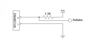
Finally, here is the circuit setup and some sample code to test the library. In the following setup, a 1.5K pull-up resister is used to power the DS28EC20. According to the datasheet, the pull-up resister must be smaller than 2.2K.

The test program writes an array of numbers (0 through 7) to the first memory page and reads back the results.
To verify that data has indeed been written into the EEPROM, you can comment out the writeMem line after the data is written and power cycle your Arduino and you should see the number you saved before.
#include <DS28EC20.h>
DS28EC20 mem(2); //DS27EC20 connected to digital pin 2

void setup()
{
    byte data[8];

    Serial.begin(9600);

    mem.init();

    for (int i = 0; i < 8; i++) {
      data[i] = i;
    }

    mem.writeMem(data, 0, 8);
    mem.readMem(data,0, 8);

    for (int i = 0; i < 8; i++) {
      Serial.print(data[i], DEC);
      Serial.print(" ");
    }
}

void loop()
{
}

