I recently dug up two sets of RF link transmitter/receiver modules from Sparkfun. I got these RF transmitters and receivers last year but have not had a chance to build anything with them yet. So I thought I would first wire up a simple transmitter/receiver to test their capabilities.
The two sets I got are 315Mhz and 434Mhz ones. While the pin layouts for these two sets are identical, they utilize different components. First off, the 434Mhz module is rated at 4800bps and the 315Mhz module is rated at 2400bps. The main difference seems to be only on the receiver side however as from a layout standpoint of view, the transmitter sides look identical. The 434Mhz receiver module is largely built from discrete components (it seems to also use one LM358 dual opamp). There is a pre-tuned tuning inductor on the reverse side of the PCB as well. The 315Mhz receiver, on the other hand, looks more integrated although operating at a lower bit rate. It uses a RX3400 ASK receiver IC.
Wiring up the modules are pretty straight forward. I quickly connected both transmitter/receiver pairs and used the following Arduino code to test their basic functionality:
//transmitter side
void setup()
{
  Serial.begin(1200);
}

void loop()
{
  Serial.println("Hello World!");
  delay(50);
}
//receiver side
void setup()
{
  Serial.begin(1200);
}

void loop()
{
  while(Serial.available() > 0) {
      Serial.print(Serial.read(), BYTE);
  }
  delay(50);
}
But it seemed that only the 434Mhz module worked.
After eliminating any possible wiring issues, I started to question whether the 315Mhz receiver was defective. So, I unconnected the output pin on the receiver from the Arduino RX pin (pin 0 on ATmega328) and hooked it directly to an oscilloscope. When I turned on the transmitter, I could clearly see on the oscilloscope that the waveform matched the encoding waveform of the message sent. So it seemed that the 315Mhz transmitter/receiver modules did work. But as soon as I connected the receiver output to the Arduino RX pin, the waveform became flat and stayed consistently at around 5V.
So it became clear that the output of the 315Mhz receiver module was unable to drive the RX pin. In Arduino, the RX pin is internally pulled high and it seemed to me that the output circuitry in the 315Mhz receiver module does not have sufficiently low output impedance to drive the internally pulled-up input pin and was only designed for direct connections with floating gates.
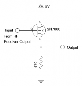
To solve this issue, I added a source follower using 2N7000 to the receiver output (see image below).

Since the source to drain resistance on the MOSFET is basically infinite, the receiver output is essentially left afloat.
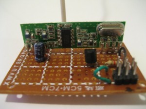
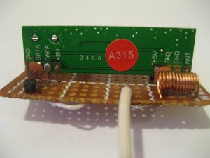
With this change, the 315Mhz modules sprang back to life. The following pictures are the receiver module with this additional source follower output buffer added.
 |
 |

