I mentioned in one of my previous posts that I decided to give PIC family MCUs a spin after having been working with AVR chips for sometime. From a pure technological stand point PIC programming and AVR programming are not all that different, especially if you are using a high level language like C. But the AVR world definitely seems to have a few advantages in the open-source arsenal such as avr-gcc and Arduino.
The lack of a comprehensive open source platform makes it more the difficult to develop products — or simply to just experiment — outside the development suite offered by Microchip. The product suite from Microchip includes Windows based MPLAB development studio and PicKit2/PicKit3 programmers which only work under MS Windows. This situation may soon change though, as a Windows/Linux version of MPLAB — MPLAB X based on NetBeans is currently in beta and presumably will enhance the cross-platform development experience.
But even with this cross-platform compatibility, the licensing for the compilers are still somewhat confusing. For instance, while MPLAB C Compiler for PIC24 has free and unrestricted evaluation version, the compiler for PIC18 does not and only offers reduced feature set for evaluation purposes. There are open-source compilers that support the PIC product line, such as SDCC, but the support level varies depending on the MCU used.
Anyway, as I do not have a PIC programmer and do not want to buy one for just a few projects I decided to build one myself. And after some research, I decided to build a USBPICProg USB PIC programmer. It is particularly attractive since it is open source in both hardware and software, and it uses an MCU (PIC18F2550) I already have.
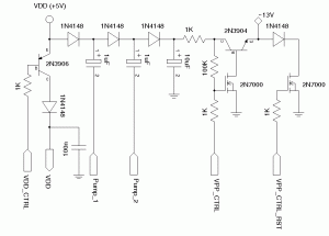
The main circuit for the USBPICProg programmer is actually quite simple. In fact, it contains nothing more than a charge pump DC/DC converter for generating the 13V programming voltage for the target MCU and everything else is accomplished in the firmware code. The reference design used a BC847 NPN transistor, two BS170 N channel MOSFETs and a more exotic P channel MOSFET TSM2301CX. These components however, can be replaced with pretty much any kind of small signal transistors or MOSFETs of the same type. I changed the components in the charge pump circuit to 2N3904 (replacing BC847), 2N3906 (replacing TSM2301CX) and 2N7000 (replacing BS170), which are more commonly available in the United States.
In theory, 2N7000 MOSFET can be replaced by an NPN BJT such as 2N3904 as well. But in this particular application, the use of N channel MOSFET 2N7000 does have its advantages since the switching voltage drop Vds(on) is almost negligible. If an NPN transistor is used instead, the Vces will be much higher.
The following schematic is the revised charge pump portion of the circuit:
And the picture below shows the completed USBPICProg board with the firmware loaded.
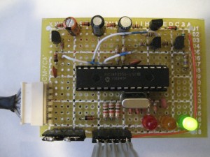
To load the firmware, I used the parallel programmer I used in one of my previous posts. The one resistor parallel programmer worked quite well and I had no problem flashing the firmware onto my PIC18F2550 for the first time.
Note that you only need to flash the firmware.hex file onto the MCU and not the boot.hex. This might not be quite clear on the official USBPICProg website.
Troubleshooting
After the firmware is in place, you should be able to use the programmer to program any other PIC MCUs via the ICSP header. Note that in normal use mode (i.e. programmer mode), VPP_SELF should be tied to Vdd (+5V) and PGC_SELF should be tied to the ground using jumpers (please refer to the USBPICProg schematics).
But if you run into any issues, I would suggest the following troubleshooting steps.
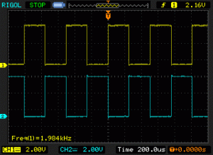
The first thing you need to make sure is that the switching capacitor stages work correctly. The easiest way to do this is using an oscilloscope to view the waveform supplied at Pump_1 and Pump_2. The firmware generates a pair of complementary square wave at roughly 2 kHz:
When VPP_CTRL_RST is driven low, the test point at the emitter of 2N3904 should have a reading of 3xVdd which is typically between 11 to 14 volts, depending on Vusb and the load.
One of the potential issues of the reference design is that if the pin controlling VPP_CTRL_RST is left float, the 2N7000 may be partially switched on due to none-zero Vgs resulted from charges being accumulated on the gate from either environmental interference or accidental touching of the gate. This will result in fluctuation of the 13 volts programming voltage as the maximum output current the charge pump circuit can supply is very low. To make this circuit more robust, you can simply connect a large resistor (e.g. 1M) between the gate and the drain of the discharging MOS FET.
USBPICProg provides a few input/output tests that you can use in conjunction with your hardware to make sure that the programmer is working as designed. For instnace, when first plugged into the USB port, the states of VPP pin, VDD pin, PGD pin and PGC pin should be as follows:

And by clicking each radio button, you should see the HW states change. Particularly, the VPP pin should change to the voltage selected as seen below:

The following pictures were taken when I used the USBPICProg to program a PIC18F4553. The red LED would flash when there is write activity and the orange LED would flash when there is read activity.
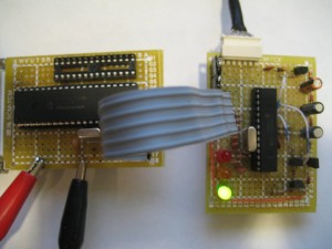
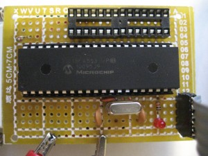
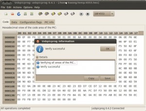
Here are a few screenshots showing a successful flash:
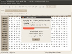
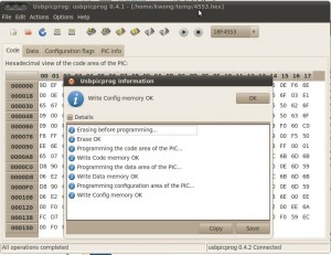
After a successful flash, you should always verify that the content has been written correctly:
