I built a 4-digit 7 segment display last year. In that design, I used four 74HC595 shift registers to drive the four individual 7 segment displays, with one for each digit. So when I wanted to build an 8-digit display, I thought about using the same design with eight 74HC595s at first. But it seemed that the soldering would be a lot more challenging on the prototype board as there will be 8 chips and 64 resistors to solder.
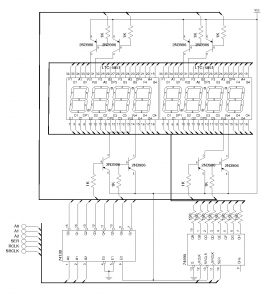
So I redesigned the circuit to multiplex the eight digits using a 74HC138 3-to-8 line decoder. Since only one digit is driven at any given time, only one 74HC595 is needed. All eight 7 segment displays share the same driving circuit. This design is shown below. I used two 4-digit 7 segment display LTC-5851 (common anode) and I used a PNP transistors to turn on and off each digit. And because we are multiplexing each digit, the same segments from all displays are connected together and sharing a single current limiting resistor. This greatly simplifies wiring.

The following Arduino code shows how to drive this display. In my example, the segments to 74HC138 outputs mapping is as follows:
7 6 5 4 3 2 1 0
A B C D E F G DP
And because of the driving circuits’ polarity, the code for the number to be displayed is the complement of the lit segments. For instance to display number “1”, segments B and C are let and thus the code is B01100000 (Hex: 60, Dec, 96). So the shifted out byte is 255-96=159. The utility I wrote (Hex/Bin/Dec Converter And Calculator) comes handy to obtain the coding for each number.
const int pinA0 = 13;
const int pinA1 = 12;
const int pinA2 = 11;
const int pinData = 10;
const int pinLatch = 9;
const int pinClk = 8;
const int segDelay = 2000;

void shiftOut(uint8_t dataPin, uint8_t clockPin, byte val)
{
  int i;

  for (i = 0; i < 8; i++)  {
    digitalWrite(dataPin, (val & _BV(i)));
    digitalWrite(clockPin, HIGH);
    digitalWrite(clockPin, LOW);
  }
}

void setup()
{
  pinMode(pinA0, OUTPUT);
  pinMode(pinA1, OUTPUT);
  pinMode(pinA2, OUTPUT);
  pinMode(pinData, OUTPUT);
  pinMode(pinLatch, OUTPUT);
  pinMode(pinClk, OUTPUT);

  digitalWrite(pinA0, HIGH);
  digitalWrite(pinA1, HIGH);
  digitalWrite(pinA2, HIGH);
  digitalWrite(pinData, HIGH);
  digitalWrite(pinLatch, HIGH);
  digitalWrite(pinClk, HIGH);
}

void loop()
{
  //8
  digitalWrite(pinA0, 0);
  digitalWrite(pinA1, 0);
  digitalWrite(pinA2, 0);
  digitalWrite(pinLatch, LOW);
  shiftOut(pinData, pinClk, 1);
  digitalWrite(pinLatch, HIGH);
  delayMicroseconds(segDelay);

  //7
  digitalWrite(pinA0, 1);

  digitalWrite(pinA1, 0);
  digitalWrite(pinA2, 0);
  digitalWrite(pinLatch, LOW);
  shiftOut(pinData, pinClk, 255-224);
  digitalWrite(pinLatch, HIGH);
  delayMicroseconds(segDelay);

  //6
  digitalWrite(pinA0, 0);
  digitalWrite(pinA1, 1);
  digitalWrite(pinA2, 0);
  digitalWrite(pinLatch, LOW);
  shiftOut(pinData, pinClk, 255-190);
  digitalWrite(pinLatch, HIGH);
  delayMicroseconds(segDelay);

  //5
  digitalWrite(pinA0, 1);
  digitalWrite(pinA1, 1);
  digitalWrite(pinA2, 0);
  digitalWrite(pinLatch, LOW);
  shiftOut(pinData, pinClk, 255-182);
  digitalWrite(pinLatch, HIGH);
  delayMicroseconds(segDelay);

  //4
  digitalWrite(pinA0, 0);
  digitalWrite(pinA1, 0);
  digitalWrite(pinA2, 1);
  digitalWrite(pinLatch, LOW);
  shiftOut(pinData, pinClk, 255-102);
  digitalWrite(pinLatch, HIGH);
  delayMicroseconds(segDelay);

  //3
  digitalWrite(pinA0, 1);
  digitalWrite(pinA1, 0);
  digitalWrite(pinA2, 1);
  digitalWrite(pinLatch, LOW);
  shiftOut(pinData, pinClk, 255-242);
  digitalWrite(pinLatch, HIGH);
  delayMicroseconds(segDelay);

  //2
  digitalWrite(pinA0, 0);
  digitalWrite(pinA1, 1);
  digitalWrite(pinA2, 1);
  digitalWrite(pinLatch, LOW);
  shiftOut(pinData, pinClk, 255-218);
  digitalWrite(pinLatch, HIGH);
  delayMicroseconds(segDelay);

  //1
  digitalWrite(pinA0, 1);
  digitalWrite(pinA1, 1);
  digitalWrite(pinA2, 1);
  digitalWrite(pinLatch, LOW);
  shiftOut(pinData, pinClk, 255-96);
  digitalWrite(pinLatch, HIGH);
  delayMicroseconds(segDelay);
}
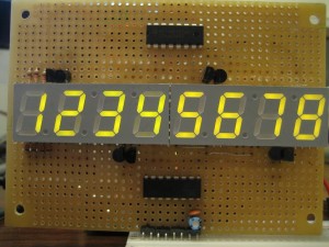
And here is the output from the display:

Final Thoughts
While the multiplexing circuit greatly reduced the number of components, it also has some disadvantages:
- Since each segment is only lit one-eighth of the time, the current limiting resistor for each segment needs to be smaller than in none-multiplexed circuit. Generally speaking, the resistor value should ensure that the current does not exceed maximum allowed current. Even though with less then unity duty cycle, we could in theory set the on-current to be greater than the maximum limit, care must be taken during circuit startup to ensure that all digits are not lit (e.g. disable 74HC138’s output) as the setup period is generally much longer than the driving frequency and there’s a greater risk of damaging the LEDs when excessive current flows through for an extended period of time. So as a result, the eight-digit display may appear slightly dimmer than when individually driven.
- Note that I added a slight delay between each digit. This is necessary due to the transistor on/off transition time. Without the delay, the lit digit will “bleed” into its neighboring digit as the transistor hasn’t fully closed but the output has already been switched to the next digit. If the transistor in use has slow on/off response, the wrong digit might be turned on if there is no delay inserted. This situation can be mitigated by using transistors designed for switching application. And adding small capacitor (e.g. 100nF) in parallel to the base resistor can also improve switching speed.

