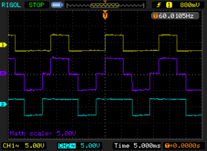
Modified sine wave is essentially just a pulse width modified square wave. It is a very useful waveform for power inverters. Compared with the simplest inverters with square waveform, inverters using modified sine wave can compensate the output voltage by simply changing the pulse width (duty cycle) of the waveform.
Modified sine wave can be generated accurately using ATMega328’s 16bit counter (counter 1) with dual-slope phase correct PWM mode. The following function generates a 60Hz modified sine wave with the given duty cycle (0 to 50). When the duty cycle equals 50, the generated output is a standard square wave. The output frequency can also be precisely controlled by changing the counter top value.
void modifiedSineWave(float dutyCycle)
{
  if (dutyCycle > 0.5) dutyCycle = 0.5;
  else if (dutyCycle < 0) dutyCycle = 0;

  cli();
  TCCR1B = _BV(WGM13) | _BV(CS11) | _BV(CS10) | _BV(ICNC1);
  //f0 = fclk / (2 * N * Top)
  long topv = (long) (F_CPU /(60.0 * 2.0 * 64.0));
  ICR1 = topv;

  OCR1A = (int) ((float) topv * dutyCycle);
  OCR1B = (int) ((float) topv * (1 - dutyCycle));
  DDRB |= _BV(PORTB1) | _BV(PORTB2);
  TCCR1A = _BV(COM1A1) | _BV(COM1B1);
  sei();
}
For more technical details, please refer to Atmel’s product documentation. The modified sine wave is outputted via PB1 and PB2 which correspond to Arduino’s digital pin 9 and digital pin 10.
Here’s an output waveform of the modified sine wave (duty cycle = 0.33) at 60Hz:

This is especially useful when used as a signal source for power inverters as two complementary outputs can be used to drive the inverter stage and the overall output waveform is modified sine.

