A signal generator can come in handy when working with digital and analog circuits. While most commercial grade signal generators offer more than just outputting a sinusoidal waveform, they are quite pricey for casual use. In this article, I will show you a simple wide band signal generator that is built around a Linear Technology’s LTC6905 Silicon Oscillator, which is can generate frequencies from roughly 17MHz to 170MHz. Along with a FairChild Semiconductor’s 74VHC4040 12-stage high speed binary counter, this signal generator is capable of generating precise frequencies from as low as 4KHz all the way through the ranges of LTC6905. The output waveform is either square wave (via the output from 74VHC4040) or sinusoidal wave (via LTC6905’s output), but should be sufficient for using as reference signals.
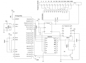
The following is the circuit diagram for this wide band signal generator:

The frequency of the LTC6905 output is determined by the divider (pin 4) setting along with the voltage applied on pin 3. To generate more stable and accurate output, I used an Analog Devices’ AD5235 1024 position digital potentiometer for the frequency adjustment. In general, digital potentiometer of at least 8 bits resolution is desired (AD5235 has a 10bit resolution) since we can get closer output frequency steps. To further automate the frequency range selection of LTC6905 (the frequency ranges are selected via the settings of the divider pin), I used a reed relay switch along with a Texas Instrument’s TS5A23159 low on-resistance analog switch to control the transitions among the three divider settings LTC6905 has to obtain a full range of the available frequencies continuously. The frequency transition is controlled by a switch (SW1) along with an ATmega328p MCU.
In order to provide frequency ranges below LTC6905’s lower range (17MHz), I used a 74VHC4040 high speed 12-stage binary counter as a frequency divider so frequencies of \[f_n = \frac{f_0}{2^n}\] can be obtained (n = 1 to 12).
One thing to keep in mind is that the output from LTC6905 is sinusoidal while the output from the frequency divider is square wave. This in general should not be of any issue when the output is used as a reference signal. In applications where the waveform requirement is strict, a high speed Schmitt Trigger may be added to LTC6905’s output.
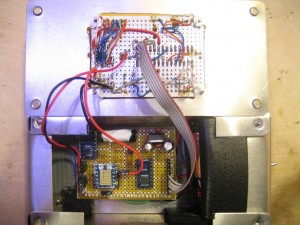
Here are a couple of pictures showing the layout of the circuits:

In the picture above, the board on the top panel consists the MCU and the 74VHC4040 and the board inside the casing consist the rest of the circuitry.
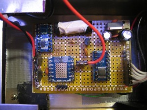
The picture below shows the layout of the signal generator. Because of the high frequencies it is operating under, I chose to enclose the whole circuit inside an aluminum case to reduce possible RF interference and thus makes the circuit more stable.

The Arduino code can be downloaded here: FreqGen.zip
In my next post, I will explain the code a little bit and show a few more pictures of this RF signal generator in action.

