Among the many commercial ISM band RF transmitter and receiver ICs, I have found that Silicon Labs‘ Si4021 (transmitter IC) and Si4311 (receiver IC) are surprisingly easy to work with. Only a few commonly available external components are needed to build a fully functional circuit. The integrated automatic antenna tunning circuit in Si4021 makes building transmitters an easy task. The Si4311 receiver IC is highly integrated, more so than many other ISM band RF ICs, and is quite tolerate to the variance of the required few external capacitors. No special tuning is required.
To test their effectiveness, I built a transmitter and a receiver using the reference designs in the data sheets. The transmitter is controlled by an ATmega328p MCU and the receiver is linked to another ATmega328p.
Here is a picture of the transmitter:
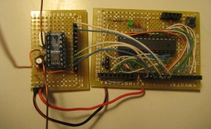
Si4021 can be used in either EPROM mode or MCU mode. In this particular application, I am using the MCU mode and the transmitter is controlled by ATmega328p. The Si4021 transmitter chip is soldered onto a SSOP breakout board, which is shown on the left. I made a simple loop antenna using magnetic wire and the power is fed through the top middle section. If you are designing a PCB based antenna, I would recommend you read this antenna design guide provided by Silicon Labs. The transmitter circuit is powered with +5V supply.
The following shows a picture of the receiver:
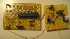
And here is a closeup of the Si4311 portion. The QFN Si4311 chip is extremely small, you can see that in my prototype I used magnetic wire to connect the solder pads to the PCB pads. I have been using this soldering technique with QFN chips to build prototypes for a while and it has been working quite well. The jumpers to the right are for the frequency deviation range settings (DEV0 and DEV1) and bit time settings (BT0 and BT1). The performance of the receiver can be fine tuned using these jumpers depending on the bit rate used. When the communication range is low, all these pins can be grounded without affecting performance too much. You can refer to the datasheet for more details.
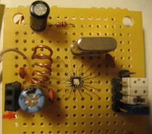
Since S4311’s maximum supply voltage is 3.6V, we cannot use the typical 5V power supply. So the Si4311 and the ATmega chip are powered using a 3.3V supply.
The receiver side of the code is fairly straight forward. Besides DEV0, DEV1, BT0 and BT1 pin settings (which are done in hardware), the receiver is totally configuration free. I used NewSoftSerial library in the code below. The main loop simply print out the incoming bit stream. You may also use Arduino’s built-in hardware serial library if you do not need the serial port for program uploading (e.g. using ICSP).
#define __AVR_ATmega328P__

#include <binary.h>
#include <HardwareSerial.h>
#include <pins_arduino.h>
#include <WConstants.h>
#include <wiring.h>
#include <wiring_private.h>
#include <WProgram.h>
#include <EEPROM/EEPROM.h>
#include <NewSoftSerial/NewSoftSerial.h>

const int PIN_RECV = 8;
const int PIN_TRAN = 7;

NewSoftSerial mySerial(PIN_RECV, PIN_TRAN);
byte b;

void setup() {
    pinMode(PIN_RECV, INPUT);
    pinMode(PIN_TRAN, OUTPUT);
    Serial.begin(9600);
    mySerial.begin(4800);
}

void loop() {
    while (mySerial.available() > 0) {
        b = mySerial.read();
        Serial.print(b);
    }
}
The transmitter side of the code is a bit more complex. As you can see in the code below, we first setup the transmitter using 433.92 Mhz frequency band, and then set the data transfer rate to 4800 bps. In the main loop, the transmitter is turned on and data is transfered using the baud rate setup earlier. For simplicity, I only used a small fraction of the available commands. Please refer to the datasheet for the full command listings.
#define __AVR_ATmega328P__

#include <binary.h>
#include <HardwareSerial.h>
#include <pins_arduino.h>
#include <WConstants.h>
#include <wiring.h>
#include <wiring_private.h>
#include <WProgram.h>
#include <EEPROM/EEPROM.h>
#include <NewSoftSerial/NewSoftSerial.h>

/** <editor-fold desc="Pin Definitions"> */
#define DATAOUT 11//1 SDI
#define DATAIN  12//
#define SPICLOCK  13//2 SCK
#define CS 10// 3

#define FSK 8
#define nIRQ 9
/** </editor-fold> */

NewSoftSerial mySerial(7, FSK);

byte spiTransfer(volatile byte data) {
    SPDR = data;

    while (!(SPSR & _BV(SPIF)));

    return SPDR;
}

void initSys() {
    pinMode(DATAOUT, OUTPUT);
    pinMode(DATAIN, INPUT);
    pinMode(SPICLOCK, OUTPUT);
    pinMode(CS, OUTPUT);
    pinMode(FSK, OUTPUT);
    pinMode(nIRQ, INPUT);

    //initialize SPI
    digitalWrite(CS, HIGH);
    SPCR = _BV(SPE) | _BV(MSTR) | _BV(CPOL);

    mySerial.begin(4800);
}

void setup() {
    initSys();

    delay(1000);

    //status registerread command
    digitalWrite(CS, LOW);
    spiTransfer(0xCC);
    spiTransfer(0x00);
    spiTransfer(0x0); // status ready at nIRQ pin
    digitalWrite(CS, HIGH);

    //configuration setting command
    //frequency band: 433
    //clock output: 10 MHz
    digitalWrite(CS, LOW);
    spiTransfer(0x8F);
    spiTransfer(0x80);
    spiTransfer(0x0);
    digitalWrite(CS, HIGH);

    //frequency setting command
    //frequency set to 433.92 MHz
    digitalWrite(CS, LOW);
    spiTransfer(0xA6);
    spiTransfer(0x20);
    spiTransfer(0x0);
    digitalWrite(CS, HIGH);

    //data rate command
    //data rate set to 4800bps
    digitalWrite(CS, LOW);
    spiTransfer(0xC8);
    spiTransfer(0x47);
    spiTransfer(0x0);
    digitalWrite(CS, HIGH);

    //low battery detector command
    //note we set the ebs bit to enable TX synchronization
    digitalWrite(CS, LOW);
    spiTransfer(0xC2);
    spiTransfer(0x20);
    spiTransfer(0x0);
    digitalWrite(CS, HIGH);

    //power management command
    //set to default: 0xC000
    digitalWrite(CS, LOW);
    spiTransfer(0xC0);
    spiTransfer(0x00);
    spiTransfer(0x0);
    digitalWrite(CS, HIGH);
}

void loop() {
    //power management command
    //turn on the crystal oscillator and the sythesizer
    //ex = 1
    //es = 1
    //turn on the power amplifier
    //ea=1
    //enable clock output buffer
    //dc=0
    digitalWrite(CS, LOW);
    spiTransfer(0xC0);
    spiTransfer(0x38);
    spiTransfer(0x0);
    digitalWrite(CS, HIGH);

    while (1) {
        mySerial.println("Hello World!");
        delay(100);
    }
}
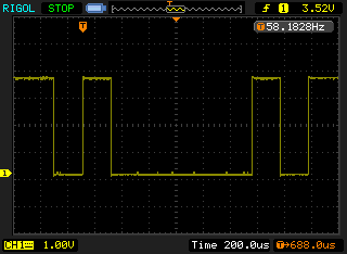
The receiver’s output conforms to the RS232 waveform standard. By default, the NewSoftSerial library uses 8 data bit 1 stop bit no parity bit and flow control is set to none. Here is the output wave form for letter “A” (B1000001).
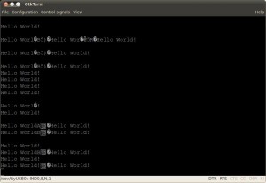
The picture below shows the receiver’s output over the serial console at 4800 kps. As you can see, the result is actually pretty good, only a few bytes are garbled. With a little bit of processing (e.g. using message checksums) the data link can be made much more reliable. Slower bit rate can also reduce error rate. If your application does not require a high data rate, you can get much less data error by simply lower the transfer data rate.
