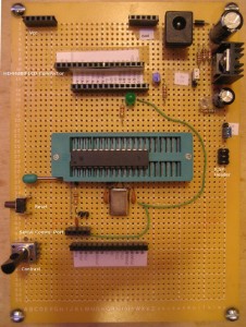
The official Arduino Duemilanove board is an excellent tool for prototyping. For most of the users, it is a very solid platform for various MCU experiment circuits given the number of readily-made shields available. But for more advanced users who need the flexibility of the official Arduino platform without the stringent header placement (required for shield interfacing) and prefer building things from the grounds up, the official board may not be the best solution.
So I decided to build my own prototyping board. Here are some of the items I wanted to address in my design:
- The ability to quickly burn code/bootloader onto new chips.
- The ability to interface with other hardwares through their native interfaces.
- The ability to work under both 5V and 3.3V.
I have been using FT232’s bitbang mode to bootload Arduino and have even built a small board just for that. As the need to program more chips arise, I have found it very time consuming to be constantly swapping chips in and out the standard IC sockets. To address this issue, I chose to use a ZIF socket in my prototyping board.
The second item mentioned above can be addressed by providing multiple headers on board (for instance, a dedicated header for the commonly used 16-pin LCD device). This way, different modules can be attached onto the MCU board easily without using a large number of jumper wires.
Since the standard Arduino runs on 5V, there is really no easy way to reduce that voltage down to 3.3V. When testing circuits with CMOS logic, this can be more than just an annoyance. To solve this problem, I chose to use an adjustable voltage regulator, with the output voltage controlled by a jumper.
Here is a picture of the finished board:

Right now, I have only one device specific header on the board (the header for LCD). Given the available space, more headers can be easily added. The power rail headers at the top can power many devices at the same time conveniently.
This board can be programmed using the standard ICSP socket or an USB-Serial adapter via the serial port with a FT232 adapter or the like. The CP2102 board I built earlier works well with this setup.

