One of my recent projects was to build a POV display device. There are already many microcontroller based POV devices out there, but most of those I have seen use around eight LEDs and have fixed font types. So I thought of developing something that is larger (e.g. using more LEDs) and more flexible (e.g. can display both text and images).
Without using any shift registers, a single ATmega328p chip can handle a around 20 I/O ports. I decided to use 16 LEDs, twice the number of LEDs as the ones you commonly see. This gives me at least four free pins for other purposes. You can probably build a POV with around 20 LEDs, but If you need more than that, you will have to use shift registers to expand the available IO pins or change to a chip that has more built-in IO pins (i.e. ATMega1280). But as you shall see later, the image generation process will be considerably more complex and the required memory storage will be much larger as well.
POV Display and Its Synchronization
In order to achieve a stable image output, the image frames generated by the POV device must be synchronized. A POV display can operate as a hand device (e.g. a wand) or be driven by a motor. When the POV device is built for hand use, it usually has a motion detector (from simple spring-in-cylinder switch to the more exotic accelerometer) so that the device can start displaying when the hand is waved. I decided to go with a motor driven design so that I can have more precise control over the output image. In this approach, image frames must be synchronized for each full rotation. A simple way to detect the motor rotation is to use a IR transmitter and receiver.
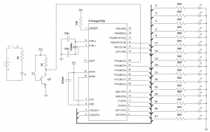
The following is the full design of my POV display (the left side shows the optical triggering mechanism mentioned above):

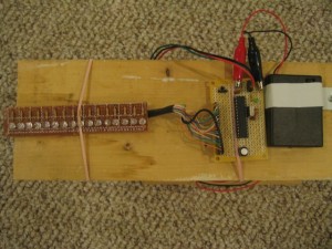
And here is the finished circuit mounted on a motorized rotating platform:

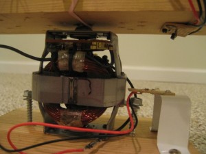
Here is a picture of the side view, you can see how the IR transmitter and receiver circuits are mounted. Whenever the transmitter and the receiver line up (it happens every rotation), the transistor would output a LOW signal to the ATMega328p (pin 28, Arduino analog pin 5) which indicates the beginning of a new frame. To reduce the light interference from the environment, the receiver is mounted on the rotor so it is facing downwards.

Image Encoder
Building the circuit is only half of the game. In order to provide the most flexible and the richest displays, I decided to build a image encoder which can be used to automatically translates a binary image into the appropriate code that is needed for the POV display. For simple POV displays, the display patterns can be mapped directly into a binary two dimensional array, with 1 represents LED on and 0 represents LED off. But this approach is not practical when displaying larger images. For an image the size of 16×100, 1600 bytes would be required to store the image information. This might not sound like much but that is almost all of ATMega328’s usable SRAM. Of course, you can always store the data structure off in Flash memory using PROGMEM, but it is not the most efficient way to do so. A better approach would be to pack these pixels into bytes so that each byte can represent 8 pixel values.
This code is shown as below. This C# code works with both Microsoft’s .Net platform or Mono.Net and thus it can be run on either Windows or Linux:
using System;
using System.Collections.Generic;
using System.Text;
using System.Drawing;
using System.Drawing.Imaging;
using System.IO;
using System.Runtime.InteropServices;

namespace convertImg
{
	class Program
	{
		static void Main (string[] args)
		{
			if (args.Length != 1) return;

			Image img = Image.FromFile (args[0]);

			Bitmap bm = new Bitmap (img);
			BitmapData bmd = bm.LockBits (new Rectangle (0, 0, img.Width, img.Height),
			                              ImageLockMode.ReadOnly, PixelFormat.Format32bppArgb);

			byte[,] ay = new byte[img.Width, img.Height];
			byte[] compactedAy = new byte[2 * img.Width];

			for (int y = 0; y < img.Height; y++) {
				for (int x = 0; x < img.Width; x++) {
					byte b = Marshal.ReadByte (bmd.Scan0, y * bmd.Stride + x * 4);

					if (b == 0)
						ay[x, y] = 1;
					else
						ay[x, y] = 0;

					Console.Write (ay[x, y]);
				}

				Console.WriteLine ();
			}

			Console.Write ("byte dispArray[] = {");

			for (int x = 0; x < img.Width; x++) {
				if (x % 8 == 0) {
					Console.WriteLine ();
					Console.Write ("\t");
				}

				compactedAy[2 * x] = (byte)(ay[x, 0] << 7 |
				                            ay[x, 1] << 6 |
				                            ay[x, 2] << 5 |
				                            ay[x, 3] << 4 |
				                            ay[x, 4] << 3 |
				                            ay[x, 5] << 2 |
				                            ay[x, 6] << 1 |
				                            ay[x, 7]);

				compactedAy[2 * x + 1] = (byte)(ay[x, 8] << 7 |
				                                ay[x, 9] << 6 |
				                                ay[x, 10] << 5 |
				                                ay[x, 11] << 4 |
				                                ay[x, 12] << 3 |
				                                ay[x, 13] << 2 |
				                                ay[x, 14] << 1 |
				                                ay[x, 15]);

				if (x < img.Width - 1) {
					Console.Write ("{0,3} ", compactedAy[2 * x]);
					Console.Write (", ");
					Console.Write ("{0,3} ", compactedAy[2 * x + 1]);
					Console.Write (", ");
				} else {
					Console.Write ("{0,3} ", compactedAy[2 * x]);
					Console.Write (", ");
					Console.Write ("{0,3} ", compactedAy[2 * x + 1]);
				}
			}

			Console.WriteLine ();
			Console.WriteLine ("};");
		}
	}
}
The code above converts a binary image into an array of packed bytes. Every vertical line consists of 16 pixels (since we are using 16 LEDs) which is translated into two consecutive bytes in the resulting array. In general, the more LEDs you have, the more space it would take for each encoded line. As you can see, making the number of LEDs divisible by eight enables us to use full bytes for each encoded line. It is possible to use number of LEDs that do not fall into this pattern, but the resulting code would be either more difficult if full byte utilization is desired or leave some unused space between each line if lines need to start on byte boundaries.
Here is our test image.

Using the image above (in PNG format) as the input, the encoded image is outputted to the terminal (formatted as a C++ array)
byte dispArray[] = {
    0, 2, 0, 30, 0, 252, 7, 240, 31, 48, 252, 48, 224, 48, 252, 48,
    31, 48, 7, 240, 0, 252, 0, 30, 0, 2, 0, 0, 0, 0, 0, 0,
    15, 254, 15, 254, 6, 0, 12, 0, 12, 0, 12, 0, 0, 0, 1, 240,
    7, 252, 14, 14, 12, 6, 12, 6, 12, 6, 12, 6, 6, 12, 255, 254,
    255, 254, 0, 0, 0, 0, 0, 0, 0, 0, 15, 248, 15, 252, 0, 14,
    0, 6, 0, 6, 0, 6, 0, 12, 15, 254, 15, 254, 0, 0, 0, 0,
    0, 0, 0, 0, 207, 254, 207, 254, 0, 0, 0, 0, 0, 0, 0, 0,
    15, 254, 15, 254, 6, 0, 12, 0, 12, 0, 12, 0, 14, 0, 7, 254,
    3, 254, 0, 0, 0, 0, 0, 0, 1, 240, 7, 252, 6, 12, 12, 6,
    12, 6, 12, 6, 12, 6, 6, 12, 7, 252, 1, 240, 0, 0, 0, 0,
    0, 0, 0, 0, 0, 0, 3, 192, 12, 48, 48, 12, 32, 4, 76, 2,
    76, 66, 128, 33, 128, 17, 128, 17, 128, 17, 76, 34, 76, 66, 32, 4,
    48, 12, 12, 48, 3, 192, 0, 0
};
and is ready to be consumed by the Arduino side of the code.
Arduino Code
And here is the code on the Arduino side (I used Netbeans as my IDE, and you may need to change a couple of the includes if you are using the IDE bundled with Arduino. For more information, please see my previous article on this.)
As you can see, the dispArray is plugged in directly from the output of the encoder shown above. Note that here I assumed the image size is 16×100, if your image widths are different, then you will need to adjust the range of curPos accordingly.
The analogRead() statement in the main loop detects whether the IR transmitter and receiver are aligned. If so, the analog pin output would become lower as the transistor on the receiver side becomes saturated and when a pre-defined threshold is crossed, the decoding process begins. Depending on how fast the display spins, colDelay may need to be adjusted accordingly.
#include <binary.h>
#include <HardwareSerial.h>
#include <pins_arduino.h>
#include <WConstants.h>
#include <wiring.h>
#include <wiring_private.h>
#include <WProgram.h>
#include <EEPROM/EEPROM.h>

const int p1 = 0; //2;
const int p2 = 1; //3;
const int p3 = 2; //4;
const int p4 = 3; //5;
const int p5 = 4; //6;
const int p6 = 5; //11;
const int p7 = 6; //12;
const int p8 = 7; //13;
const int p9 = 8; //14;
const int p10 = 9; //15;
const int p11 = 10; //16;
const int p12 = 14; //23;
const int p13 = 15; //24;
const int p14 = 16; //25;
const int p15 = 17; //26;
const int p16 = 18; //27;

const int triggerPin = 5; //28;

const int colDelay = 8;

int ledPins[] = {p1, p2, p3, p4, p5, p6, p7, p8, p9, p10, p11, p12, p13, p14, p15, p16};
int curPos = 0;

/** Image generator output */
byte dispArray[] = {
    0, 2, 0, 30, 0, 252, 7, 240, 31, 48, 252, 48, 224, 48, 252, 48,
    31, 48, 7, 240, 0, 252, 0, 30, 0, 2, 0, 0, 0, 0, 0, 0,
    15, 254, 15, 254, 6, 0, 12, 0, 12, 0, 12, 0, 0, 0, 1, 240,
    7, 252, 14, 14, 12, 6, 12, 6, 12, 6, 12, 6, 6, 12, 255, 254,
    255, 254, 0, 0, 0, 0, 0, 0, 0, 0, 15, 248, 15, 252, 0, 14,
    0, 6, 0, 6, 0, 6, 0, 12, 15, 254, 15, 254, 0, 0, 0, 0,
    0, 0, 0, 0, 207, 254, 207, 254, 0, 0, 0, 0, 0, 0, 0, 0,
    15, 254, 15, 254, 6, 0, 12, 0, 12, 0, 12, 0, 14, 0, 7, 254,
    3, 254, 0, 0, 0, 0, 0, 0, 1, 240, 7, 252, 6, 12, 12, 6,
    12, 6, 12, 6, 12, 6, 6, 12, 7, 252, 1, 240, 0, 0, 0, 0,
    0, 0, 0, 0, 0, 0, 3, 192, 12, 48, 48, 12, 32, 4, 76, 2,
    76, 66, 128, 33, 128, 17, 128, 17, 128, 17, 76, 34, 76, 66, 32, 4 of,
    48, 12, 12, 48, 3, 192, 0, 0
};

/**
 * delay ms * 0.1 milliseconds
 */
void delayMilliseconds(int ms) {
    for (int i = 0; i < ms; i++) {
        delayMicroseconds(100);
    }
}

void setup() {
    for (int i = 0; i < 16; i++) {
        pinMode(ledPins[i], OUTPUT);
        digitalWrite(ledPins[i], LOW);
    }
}

void loop() {
    if (analogRead(triggerPin) < 800) {
        for (int curPos = 99; curPos >= 0; curPos--) {
            byte b1 = dispArray[curPos * 2];
            byte b2 = dispArray[curPos * 2 + 1];

            for (int i = 0; i < 8; i++) {
                digitalWrite(ledPins[i + 8], (b1 & (1 << i)) >> i);
                digitalWrite(ledPins[i], (b2 & (1 << i)) >> i);
            }

            delayMilliseconds(colDelay);
        }

        for (int i = 0; i < 16; i++) {
            digitalWrite(ledPins[i], LOW);
        }
    }
}
POV Display in Action
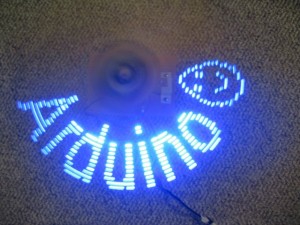
Here’s the POV display in action. Using the programs in this article what you can show on this POV display is not just limited to characters, any binary image design that fits the image dimension (16×100 in this example) can be used. If you use different images for different frames you can even create your own POV animation.


