DS89C430 and DS89C450 are two ultra-high-speed 8051-compatible microcontrollers from Maxim Integrated Products. One unique feature of DS89C430/450 microcontroller is that it has a ROM loader mode which can be used to program the microcontroller itself.
According to the user’s guide, UART0 (pin 10 and pin 11) is invoked in ROM loader mode when RST is set to High and both EA and PSEN are set to LOW simultaneously. After the ROM loader mode is enabled, serial communication can be handled between a PC’s RS-232 port and the microcontroller using a RS-232 transmitter/receiver such as DS232A.
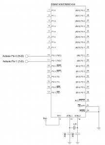
It is also possible to communicate with DS89C430/450’s using PC’s USB port with a USB UART converter IC such as FTDI’s FT232R. If you have an Arduino, then you can just use the on-board FT232RL for this purpose. Technically speaking, this has little to do with Arduino as you could just use an FT232R adapter board, but with Arduino the RX/TX pins are readily accessible (pin 0 and pin 1) and thus using Arduino as a USB to UART converter couldn’t have been any easier. The basic schematic for using Arduino to invoke the DS89C430/450’s ROM loader mode is shown below:

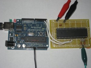
Please note that DS89C430/450’s RX pin is connected to the socket on the Arduino board marked with RX and the TX pin is connected to the socket marked with TX. This is because Arduino’s RX socket is actually connected to the TX pin (pin 1) of FT232RL and TX socket is connected to the RX (pin 5) of FT232RL. The picture below shows how this is setup between an DS89C430 and Arduino (I used an external 5V supply here for the DS89C430 board, but you can use the 5V pin directly from the Arduino board if you want to).

According to the user guide, DS89C430/450’s ROM loader automatically tries baud rates generated by this equation:
\[ROM Loader Baud Rate = \frac{Crystal Frequency}{192\times(256-Timer Reload)}\]
And the timer reload values attempted by the loader are: FF, FE, FD, FC, FB, FA, F8, F6, F5, F4, F3, F0, EC, EA, E8, E6, E0, DD, D8, D4, D0, CC, C0, BA, B0, A8, A0, 98, 80, 60, 40. In order for a given generated baud rate to work, the error between the generated baud rate and the UART’s baud rate must be less than 3%.
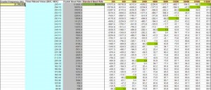
To make the selection of crystal frequency easier, I developed a spreadsheet that can be used to determine which standard baud rate a particular crystal can operate under. You can simply plugin the crystal frequency you intend to use and the supported baud rates are automatically highlighted in green (see screenshot below).

This spreadsheet can be downloaded here:
baudratecalc.ods (OpenOffice)
baudratecalc.xls (Excel)
The crystal frequency I used is 21.7 Mhz which as you can see in the screenshot above supports most of the standard baud rates.
I use PuTTY for the serial communication with the following parameters (note the speed must be one of the supported baud rate calculated above, it depends on the crystal you use). You can use gtkterm as well.
Serial line to connect to: /dev/ttyUSB0
Speed: 115200
Data bits: 8
Stop bits: 1
Parity: None
Flow control: None
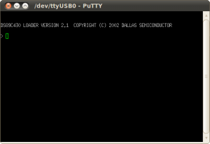
And here’s a screen shot of DS89C430 in ROM loader mode:

When the microcontroller is in ROM loader mode, programs can be uploaded using the ROM loader command interface mentioned in the user guide.

