Over the past couple of weeks, I have been experimenting with BQ3287, a real time clock module from Taxes Instruments. My ultimate goal was to eventually create a full fledged control platform based on this RTC module (more on this later). But first and foremost, I would like to explore its capabilities as an accurate time keeper.
The BQ3287 model by itself is really easy to interface with MCUs. There is a nice tutorial on how to use BQ3287 with Arduino and some of the code I am using in this post is borrowed from that project. The main difficulty of turning BQ3287 into a full-fledged clock is that this RTC module uses up to 16 digital pins out of 20 usable pins an ATMega328p has, which leaves very few pins for display and control purposes. After toying with a few possible designs, I decided to use 13 out of the 16 pins so that no major functionality is sacrificed (MOT is left disconnected using Intel bus timing, RESET is tied to Vcc and CS is connected to ground).
Digital pin 0 and 1 (chip pin 1 and 2) are used for button input. Since these two pins are also used as serial RX TX pair when used with the Arduino (the FT232RL chip communicates to The ATmega328 via these two pins) board, I resorted to the ICSP method to program the chip without using the Arduino board.
With this setup, we have two additional pins (pin 27 and 28, these are analog pin 4 and 5 on the Arduino board) available. Since these two pin s are the SCL and SDA pins in TWI (I2C) communication, I am planning to use them to communicate to another ATmega328 chip to further expand the functionality of this clock in the future.
For now, I am using the two buttons to multiplex the following functions:
- Display Time
- Display Date
- Display Year
- Stop Watch
- Change Time Setting
- Change Date Setting
- Change Year Setting
Please see the comment in the code section below to see how these functionalities are achieved.
Three pins are used to control the 4 7 segment display I made earlier. The display update is triggered by the interrupt signal generated from the SQW output pin of BQ3287, I set the interrupt frequency to 128 Hz (RS3 RS2 RS1 RS0 = 1001) to ensure the accuracy of the stop watch (0.1 second) while still maintain a reasonable overhead. The update code all resides in the interrupt handler (intr()).
As you can see in the code, dot between the hour and minute display is turned on and off on a half second interval and in change settings mode the values to be changed also flashes at a half second interval.
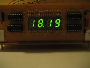
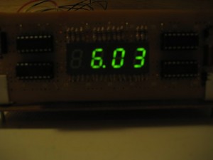
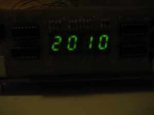
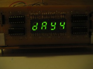
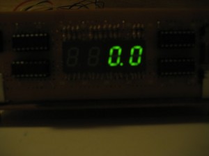
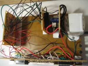
Here are some pictures showing the clock displaying in various modes. And the last picture shows the board setup: the front board houses the 4 7 segment display, the left side is the ATmega328 board, the middle one contains the BQ3287 module and the right side board is the voltage regulator board. I used a Taxes Instrument TL720M05 LDO linear voltage regulator, which is a nice LDO pin compatible replacement of the good old 7805.
 |
 |
 |
 |
 |
 |
And here’s the code listing for this project. As mentioned earlier, I am planing to use a separate ATmega328 board to communicate with this clock using TWI so that I can setup timers/alarms to control other electronics.
//define the bidirectional address-data bus
const int ad0 = 3; //chip pin 5
const int ad1 = 4; //chip pin 6
const int ad2 = 5; //chip pin 11
const int ad3 = 6; //chip pin 12
const int ad4 = 7; //chip pin 13
const int ad5 = 8; //chip pin 14
const int ad6 = 9; //chip pin 15
const int ad7 = 10; //chip pin 16

//ALE or address strobe (AS pin)
const int as = 11; //chip pin 17
//WR or (RW pin)
const int rw = 12; //chip pin 18
//RD or OE (DS pin )
const int ds = 13; //chip pin 19
//interrupt request
const int irq = 14; //chip pin 23

//7-seg display pins
const int clockPin = 15; //chip pin 24
const int latchPin = 16; //chip pin 25
const int dataPin = 17; //chip pin 26

//control button pins
//Note, since these are the rx/tx pins when using FT232RL
//you will either have to program the chip using a programmer (the method I used)
//or using the remaining two two analog data pins (18 and 19). But then you are
//lossing two pins to work with.
const int btnPin1 = 0; //chip pin 1
const int btnPin2 = 1; //chip pin 2

const int COMMON_ANODE = 1; //1 CA, 0 CC

//bq3287 registers
const int regA = 0x0A;
const int regB = 0x0B;

//RO registers C,D
const int regC = 0x0C;
const int regD = 0x0D;

const int ADDR_CUR_SEC = 0;
const int ADDR_ALM_SEC = 1;
const int ADDR_CUR_MIN = 2;
const int ADDR_ALM_MIN = 3;
const int ADDR_CUR_HOUR = 4;
const int ADDR_ALM_HOUR = 5;
const int ADDR_CUR_DOW = 6;
const int ADDR_CUR_DAY = 7;
const int ADDR_CUR_MON = 8;
const int ADDR_CUR_YEAR = 9;

//display modes
//button 1 has 4 modes
const int DM_TIME = 0; //display time
const int DM_DATE = 1; //display date
const int DM_YEAR = 2; //display year
const int DM_DOW = 3; //display day of the week
const int DM_STOP_WATCH = 4; //display stop watch

//button 2 has 7 modes
const int DM_ADJ_NONE = 0; //display the current time
const int DM_ADJ_HOUR = 1; //adjust hour
const int DM_ADJ_MIN = 2; //adjust minute
const int DM_ADJ_MONTH = 3; //adjust month
const int DM_ADJ_DAY = 4; //adjust day
const int DM_ADJ_YEAR = 5; //adjust year
const int DM_ADJ_DOW = 6; //adjust day of the week

/** global variables for storing button's current mode.
 * Button functions
 * When button 2 is not pressed (in DM_ADJ_NONE)
 * press button 1 will cycle through the following display modes:
 *      current time (default)
 *      current date
 *      current year
 *      stop watch
 * when in stop watch mode, button 1 is used to start/stop/reset the stop watch.
 *
 * while in display current time mode (button 1 mode equals DM_TIME)
 * press button 2 will cycle through the following adjustment modes:
 *      adjust hour
 *      adjust minute
 *      adjust month
 *      adjust day
 *      adjust year
 *      adjust day of week
 * when in adjustment mode, button 1 is used to increment the settings.
 */
int btnMode1 = 0;
int btnMode2 = 0;

boolean btn1Pressed = false;
boolean btn2Pressed = false;

//stop watch initialization indicator, if this is set to true
//the stop watch is stopped and displays 0.0
boolean stopWatchInit = true;
boolean stopWatchStarted = false;

/** 7seg character mapping char <-> code */
struct CharMap {
    char c;
    byte v;
};

//the length of the character map, it must match
//the cmap[] array lengh below
const int cmap_len = 41;

//defines the 7seg display characters
struct CharMap cmap[] = {
    {' ', 0},
    {'1', 96},
    {'2', 218},
    {'3', 242},
    {'4', 102},
    {'5', 182},
    {'6', 190},
    {'7', 224},
    {'8', 254},
    {'9', 246},
    {'0', 252},
    {'A', 238},
    {'b', 62},
    {'c', 26},
    {'C', 156},
    {'d', 122},
    {'e', 222},
    {'E', 158},
    {'F', 142},
    {'g', 246},
    {'H', 110},
    {'h', 46},
    {'I', 96},
    {'J', 120},
    {'L', 28},
    {'n', 42},
    {'o', 58},
    {'P', 206},
    {'q', 230},
    {'r', 10},
    {'S', 182},
    {'t', 30},
    {'u', 56},
    {'U', 124},
    {'y', 118},
    {'-', 2},
    {'~', 128},
    {'_', 16},
    {'.', 1},
    {'|', 108},
    {'=', 144}
};

//indicates whether the led on 7seg indicating the "seconds" is on
boolean secondIndLEDOn = false;

//arrays for date/time conversion
char hour[2], minute[2], seconds[6];
char year[2], month[2], day[2], dow[1];

//the 4 characters on the 7seg
char c1, c2, c3, c4;

//this counter is incremented whenever the SW output pin
//triggers the interrupt
int interruptConter = 0;

//this counter is used to keep track of time in stop watch mode
unsigned int stopWatchCounter = 0;

/** same as delay() but works with interrupts */
void delayMilliseconds(int ms) {
    for (int i = 0; i < ms; i++) {
        delayMicroseconds(1000);
    }
}

/** get the display code for a character
/* it looks through the charactor map and find a match that corresponds to c
/* if no match is found, it returns 2 (corresponding to character '-') */
byte getCharDisplayCode(char c) {
    byte r = 2;

    for (int i = 0; i < cmap_len; i++) {
        if (c == cmap[i].c) {
            r = cmap[i].v;
            break;
        }
    }

    return r;
}

/** initialize the display
/* when the 7seg display is initialized, display nothing */
void init7seg() {
    pinMode(latchPin, OUTPUT);
    pinMode(clockPin, OUTPUT);
    pinMode(dataPin, OUTPUT);

    disp(' ', false, ' ', false, ' ', false, ' ', false);
}

/** this essentially is the library function shiftOut, it can be customized if
/* it is needed.
/* it works with 74HC595 (serial in, parallel out) */
void shiftOut(uint8_t dataPin, uint8_t clockPin, byte val) {
    int i;

    for (i = 0; i < 8; i++) {
        digitalWrite(dataPin, (val & _BV(i)));
        digitalWrite(clockPin, HIGH);
        digitalWrite(clockPin, LOW);
    }
}

/* display the characters on the 7seg
/* the boolean value between characters indicates whether to light up the
/* decimal point */
void disp(char c1, boolean dot1, char c2, boolean dot2, char c3, boolean dot3, char c4, boolean dot4) {
    byte b1 = getCharDisplayCode(c1);
    byte b2 = getCharDisplayCode(c2);
    byte b3 = getCharDisplayCode(c3);
    byte b4 = getCharDisplayCode(c4);

    if (dot1 == true) b1 += 1;
    if (dot2 == true) b2 += 1;
    if (dot3 == true) b3 += 1;
    if (dot4 == true) b4 += 1;

    if (COMMON_ANODE == 1) {
        b1 = 255 - b1;
        b2 = 255 - b2;
        b3 = 255 - b3;
        b4 = 255 - b4;
    }

    digitalWrite(latchPin, LOW);

    shiftOut(dataPin, clockPin, b4);
    shiftOut(dataPin, clockPin, b3);
    shiftOut(dataPin, clockPin, b2);
    shiftOut(dataPin, clockPin, b1);

    digitalWrite(latchPin, HIGH);
}

/** convert a number (maximum 2 digita) to a character array
/* returning the length of the converted char array
/* this is used to convert hour/minutes into characters for display */
int convertToCharAarray(byte num, char *dest) {
    sprintf(dest, "%d", num);

    if (num < 10) return 1;
    else if (num < 100 && num >= 10) return 2;
    else return -1;
}

/** displays the current time on 7seg,
/* the display mode is controlled by the states of the button states */
void dispCurrentTime() {
    if (!bitRead(readbyte(regA), 7)) {
        byte h = readbyte(ADDR_CUR_HOUR);
        byte m = readbyte(ADDR_CUR_MIN);

        byte l1 = convertToCharAarray(h, hour);
        byte l2 = convertToCharAarray(m, minute);

        if (l1 == 1) {
            c2 = ' ';
            c1 = hour[0];
        } else {
            c1 = hour[1];
            c2 = hour[0];
        }

        if (l2 == 1) {
            c4 = '0';
            c3 = minute[0];
        } else {
            c3 = minute[1];
            c4 = minute[0];
        }
    }

    disp(c2, false, c1, secondIndLEDOn, c4, false, c3, false);

    switch (btnMode2) {
        case DM_ADJ_NONE: //normal display mode, displays time
            disp(c2, false, c1, secondIndLEDOn, c4, false, c3, false);
            break;
        case DM_ADJ_HOUR: //if adjust hour, flash the hour digits
            if (secondIndLEDOn)
                disp(' ', false, ' ', true, c4, false, c3, false);
            else
                disp(c2, false, c1, true, c4, false, c3, false);
            break;
        case DM_ADJ_MIN: //if adjust minutes, flash the minute digits
            if (secondIndLEDOn)
                disp(c2, false, c1, true, ' ', false, ' ', false);
            else
                disp(c2, false, c1, true, c4, false, c3, false);
            break;
    }
}

/** displays in stop watch mode. */
void dispStopWatch() {
    for (int i = 0; i < 5; i++) seconds[i] = ' ';

    int i = (int) (((float) (stopWatchCounter) / 128.0) * 10.0 + 0.5);
    sprintf(seconds, "%6d", i);

    if (stopWatchInit) {
        disp(' ', false, ' ', false, '0', true, '0', false);
    } else {
        if (stopWatchCounter < 128) { //less than 1 second, displays the leading 0
            disp(seconds[2], false, seconds[3], false, '0', true, seconds[5], false);
        } else {
            disp(seconds[2], false, seconds[3], false, seconds[4], true, seconds[5], false);
        }
    }
}

/** displays current date */
void dispCurrentDate() {
    if (!bitRead(readbyte(regA), 7)) {
        byte m = readbyte(ADDR_CUR_MON);
        byte d = readbyte(ADDR_CUR_DAY);

        byte l1 = convertToCharAarray(m, month);
        byte l2 = convertToCharAarray(d, day);

        if (l1 == 1) {
            c2 = ' ';
            c1 = month[0];
        } else {
            c1 = month[1];
            c2 = month[0];
        }

        if (l2 == 1) {
            c4 = '0';
            c3 = day[0];
        } else {
            c3 = day[1];
            c4 = day[0];
        }
    }

    switch (btnMode2) {
        case DM_ADJ_NONE: //normal display mode, displays date
            disp(c2, false, c1, true, c4, false, c3, false);
            break;
        case DM_ADJ_MONTH: //if adjust month, flash the month digits
            if (secondIndLEDOn)
                disp(' ', false, ' ', true, c4, false, c3, false);
            else
                disp(c2, false, c1, true, c4, false, c3, false);
            break;
        case DM_ADJ_DAY: //if adjust day, flash the day digits
            if (secondIndLEDOn)
                disp(c2, false, c1, true, ' ', false, ' ', false);
            else
                disp(c2, false, c1, true, c4, false, c3, false);
            break;
        default:
            break;
    }

}

/** displays the current year (e.g. 2010) */
void dispCurrentYear() {
    if (!bitRead(readbyte(regA), 7)) {
        byte y = readbyte(ADDR_CUR_YEAR);

        byte l1 = convertToCharAarray(y, year);

        c2 = '2';
        c1 = '0';

        if (l1 == 1) {
            c4 = '0';
            c3 = year[0];
        } else {
            c3 = year[1];
            c4 = year[0];
        }
    }

    switch (btnMode2) {
        case DM_ADJ_NONE:
            disp(c2, false, c1, false, c4, false, c3, false);
            break;
        case DM_ADJ_YEAR:
            if (secondIndLEDOn)
                disp(c2, false, c1, false, ' ', false, ' ', false);
            else
                disp(c2, false, c1, false, c4, false, c3, false);
            break;
        default:
            break;
    }

}

/** displays the day of the week (e.g. day1 for Monday) */
void dispDayOfWeek() {
    if (!bitRead(readbyte(regA), 7)) {
        byte d = readbyte(ADDR_CUR_DOW);

        convertToCharAarray(d, dow);
    }

    switch (btnMode2) {
        case DM_ADJ_NONE: //normal display mode
            disp('d', false, 'A', false, 'y', false, dow[0], false);
            break;
        case DM_ADJ_DOW: //if adjust day of the week, flash the digit
            if (secondIndLEDOn)
                disp('d', false, 'A', false, 'y', false, ' ', false);
            else
                disp('d', false, 'A', false, 'y', false, dow[0], false);
            break;
    }
}

/** set the clock bus mode
/* INPUT or OUTPUT */
void setClkBusMode(int mode) {
    pinMode(ad0, mode);
    pinMode(ad1, mode);
    pinMode(ad2, mode);
    pinMode(ad3, mode);
    pinMode(ad4, mode);
    pinMode(ad5, mode);
    pinMode(ad6, mode);
    pinMode(ad7, mode);
}

/** read a byte from address */
byte readbyte(byte address) {
    byte readb = 0;

    //set address pins to output
    setClkBusMode(OUTPUT);
    //start READ cycle
    digitalWrite(rw, HIGH);
    //prepare to set address on bus
    digitalWrite(ds, HIGH);
    //delayMicroseconds(1);
    //set ALE high, on fall address latches
    digitalWrite(as, HIGH);

    //set address on bus
    digitalWrite(ad0, bitRead(address, 0));
    digitalWrite(ad1, bitRead(address, 1));
    digitalWrite(ad2, bitRead(address, 2));
    digitalWrite(ad3, bitRead(address, 3));
    digitalWrite(ad4, bitRead(address, 4));
    digitalWrite(ad5, bitRead(address, 5));
    digitalWrite(ad6, bitRead(address, 6));
    digitalWrite(ad7, bitRead(address, 7));

    //set ALE low, latch address
    digitalWrite(as, LOW);
    setClkBusMode(INPUT);
    //finish address setting
    digitalWrite(ds, LOW);
    //wait for data from address
    //set bus for input
    //start reading data
    readb = digitalRead(ad0) | (digitalRead(ad1) << 1) | (digitalRead(ad2) << 2) | (digitalRead(ad3) << 3) | (digitalRead(ad4) << 4) | (digitalRead(ad5) << 5) | (digitalRead(ad6) << 6) | (digitalRead(ad7) << 7);
    digitalWrite(ds, HIGH);

    return readb;
}

/** write a byte to address */
void writebyte(byte address, byte value) {
    //set address pins to output
    setClkBusMode(OUTPUT);
    //start READ cycle
    digitalWrite(rw, HIGH);
    //prepare to set address on bus
    digitalWrite(ds, HIGH);
    //set ALE high, on fall address latches
    digitalWrite(as, HIGH);
    //set address on bus
    digitalWrite(ad0, bitRead(address, 0));
    digitalWrite(ad1, bitRead(address, 1));
    digitalWrite(ad2, bitRead(address, 2));
    digitalWrite(ad3, bitRead(address, 3));
    digitalWrite(ad4, bitRead(address, 4));
    digitalWrite(ad5, bitRead(address, 5));
    digitalWrite(ad6, bitRead(address, 6));
    digitalWrite(ad7, bitRead(address, 7));
    digitalWrite(as, LOW);
    digitalWrite(rw, LOW);
    //set byte to write
    digitalWrite(ad0, bitRead(value, 0));
    digitalWrite(ad1, bitRead(value, 1));
    digitalWrite(ad2, bitRead(value, 2));
    digitalWrite(ad3, bitRead(value, 3));
    digitalWrite(ad4, bitRead(value, 4));
    digitalWrite(ad5, bitRead(value, 5));
    digitalWrite(ad6, bitRead(value, 6));
    digitalWrite(ad7, bitRead(value, 7));
    digitalWrite(rw, HIGH);
}

/** adjust a register value by 1*/
boolean adjust(byte address) {
    //read current value
    byte value = 0;
    byte b;
    if ((address < 0) || (address > 10)) return false;
    if (!bitRead(readbyte(regA), 7)) value = readbyte(address);
    b = readbyte(regB);
    //set SET bit of register B that will prevent double buffer update from internal buffer
    b = b | 0x80;
    writebyte(regB, b);

    if (bitRead(readbyte(regB), 7)) {
        switch (address) {
            case ADDR_CUR_SEC://seconds
                writebyte(address, 0); //reset
                break;
            case ADDR_ALM_SEC://seconds alarm
                writebyte(address, 0); //reset
                break;
            case ADDR_CUR_MIN://minutes
                if (value >= 59) {
                    writebyte(address, 0);
                } else {
                    value++;
                    writebyte(address, value);
                }
                break;
            case ADDR_ALM_MIN://minutes alarm
                if (value >= 59) {
                    writebyte(address, 0);
                } else {
                    value++;
                    writebyte(address, value);
                }
                break;
            case ADDR_CUR_HOUR://hours
                if (value >= 23) {
                    writebyte(address, 0);
                } else {
                    value++;
                    writebyte(address, value);
                }
                break;
            case ADDR_ALM_HOUR://hours alarm
                if (value >= 23) {
                    writebyte(address, 0);
                } else {
                    value++;
                    writebyte(address, value);
                }
                break;
            case ADDR_CUR_DOW://day of week
                if (value >= 7) {
                    writebyte(address, 1);
                } else {
                    value++;
                    writebyte(address, value);
                }
                break;
            case ADDR_CUR_DAY:
                if (value >= 31) {
                    writebyte(address, 1);
                } else {
                    value++;
                    writebyte(address, value);
                }
                break;
            case ADDR_CUR_MON://month
                if (value >= 12) {
                    writebyte(address, 1);
                } else {
                    value++;
                    writebyte(address, value);
                }
                break;
            case ADDR_CUR_YEAR://year
                if (value == 99) {
                    writebyte(address, 0);
                } else {
                    value++;
                    writebyte(address, value);
                }
                break;
        }
    }

    //mask regA and clear SET bit
    b = b & 0x7F;
    writebyte(regB, b);
    return true;
}

/** interrupt handler routine */
void intr() {
    interruptConter++;

    if (stopWatchStarted) {
        stopWatchCounter++;
    }

    switch (btnMode1) {
        case DM_TIME:
            switch (btnMode2) {
                case DM_ADJ_NONE:
                    dispCurrentTime();
                    break;
                case DM_ADJ_HOUR:
                    dispCurrentTime();
                    break;
                case DM_ADJ_MIN:
                    dispCurrentTime();
                    break;
                case DM_ADJ_MONTH:
                    dispCurrentDate();
                    break;
                case DM_ADJ_DAY:
                    dispCurrentDate();
                    break;
                case DM_ADJ_YEAR:
                    dispCurrentYear();
                    break;
                case DM_ADJ_DOW:
                    dispDayOfWeek();
                    break;
            }
            break;
        case DM_DATE:
            dispCurrentDate();
            break;
        case DM_YEAR:
            dispCurrentYear();
            break;
        case DM_DOW:
            dispDayOfWeek();
            break;
        case DM_STOP_WATCH:
            dispStopWatch();
            break;
        default:
            break;
    }

    //flashes the second indicator (the dot) every half second
    if (interruptConter > 63) {
        interruptConter = 0;
        secondIndLEDOn = !secondIndLEDOn;
    }
}

/*********************
 * Arduino routines
 *********************/
void setup() {
    init7seg();
    pinMode(btnPin1, INPUT);
    pinMode(btnPin2, INPUT);
    digitalWrite(btnPin1, HIGH);
    digitalWrite(btnPin2, HIGH);

    pinMode(as, OUTPUT);
    pinMode(ds, OUTPUT);
    pinMode(rw, OUTPUT);

    //delay after power up to start-up
    digitalWrite(as, LOW);
    digitalWrite(ds, LOW);
    digitalWrite(rw, LOW);
    delayMicroseconds(200);

    // RS3 RS2 RS1 RS0 = 1001 set SQW output frequency to 128 Hz
    byte a = 41;
    writebyte(regA, a);

    byte b = readbyte(regB);
    b = b | 0xF;
    writebyte(regB, b);

    attachInterrupt(0, intr, RISING);
    c1 = ' ';
    c2 = ' ';
    c3 = ' ';
    c4 = ' ';
}

void loop() {
    if (digitalRead(btnPin1) == LOW && !btn1Pressed) {//debouncing btn1
        delayMilliseconds(20);
        if (digitalRead(btnPin1) == LOW) {
            switch (btnMode2) {
                case DM_ADJ_NONE:
                    btnMode1 = (btnMode1 + 1) % 5;
                    break;
                case DM_ADJ_HOUR:
                    adjust(ADDR_CUR_HOUR);
                    break;
                case DM_ADJ_MIN:
                    adjust(ADDR_CUR_MIN);
                    break;
                case DM_ADJ_MONTH:
                    adjust(ADDR_CUR_MON);
                    break;
                case DM_ADJ_DAY:
                    adjust(ADDR_CUR_DAY);
                    break;
                case DM_ADJ_YEAR:
                    adjust(ADDR_CUR_YEAR);
                    break;
                case DM_ADJ_DOW:
                    adjust(ADDR_CUR_DOW);
                    break;
                default:
                    break;
            }

            btn1Pressed = true;
        }
    }

    if (digitalRead(btnPin1) == HIGH) {
        delayMilliseconds(20);

        if (digitalRead(btnPin1) == HIGH) {
            btn1Pressed = false;
        }
    }

    if (digitalRead(btnPin2) == LOW && !btn2Pressed) {
        delayMilliseconds(20);

        if (digitalRead(btnPin2) == LOW) {//debouncing btn2
            if (btnMode1 == DM_TIME) {
                btnMode2 = (btnMode2 + 1) % 7;
            }

            if (btnMode1 == DM_STOP_WATCH && !stopWatchStarted && stopWatchInit) {
                stopWatchInit = false;
                stopWatchStarted = true;
            } else if (btnMode1 == DM_STOP_WATCH && stopWatchStarted && !stopWatchInit) {
                stopWatchStarted = false;
            } else if (btnMode1 == DM_STOP_WATCH && !stopWatchStarted && !stopWatchInit) {
                stopWatchInit = true;
                stopWatchCounter = 0;
            }

            btn2Pressed = true;
        }
    }

    if (digitalRead(btnPin2) == HIGH) {//debouncing btn2
        delayMilliseconds(20);
        if (digitalRead(btnPin2) == HIGH) {
            btn2Pressed = false;
        }
    }
}

