I have been using the bit-banging method to boot-load ATmega328p with Arduino bootloader for a while, and Kimo’s method worked quite well for me. If you need to flash a lot of chips however, you might not want to swap out the chip on your Arduino board every single time you need to flash another chip as you do not want to accidentally damage the socket (or the board) in the process. After all, the DIP socket is not designed for this kind of repetitive use.
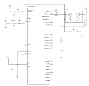
So, I decided to make a separate ICSP board just for programming ATmega328p. The concept is quite simple, as you can see in the schematics below it basically is a bare bone ATmega328 board with a reset button and ICSP headers. I added an LED to pin 19 (Arduino pin 13) so that if the boot loader is flashed successfully, the LED will blink just as would on an Arduino board. The LED will also serve as an indicator during flashing.
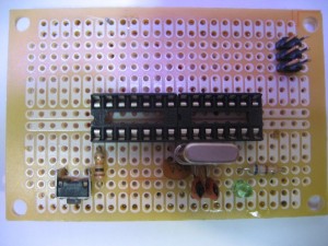
The following is the board with the ICSP header based on the schematics shown above. This board is not just limited to burning Arduino boot loader or other Arduino programs though, it can serve as a standard template for any ATmega328 based system you build. Ideally, you probably want to replace the standard DIP socket with a ZIF socket so that it is more suitable to be used as a programmer board.
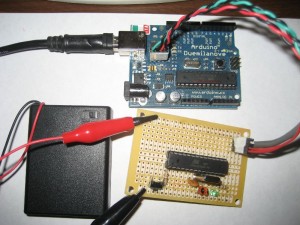
Here is a picture taken while I was testing flashing boot loader with the bit-banging method. Since I kept the ICSP header pin layout the same as on the Arduino board, I can use the same cable as I used before. You can find more details on how to make the cable and here.
I decided to add voltage regulation circuitry so that I can use different power sources. The finished ICSP board with case is shown below:
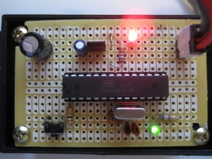
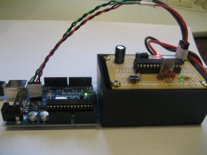
Here’s another picture of the ICSP board in action:
And of course, you can also use a regular programmer to program chips on this ICSP board as well.

