In my last post, I described in detail how to hand solder LIS3LV02DL, an LGA packaged accelerometer chip. And here I will show you how the communication with Arduino is done using SPI.
Before I start, I should mention that according to the product documentation, the normal operation voltage (Vdd) for LIS3LV02DL is between 2.16V and 3.6V. Ideally you should interface LIS3LV02DL with CMOS logic level rather than the standard TTL logic level Arduino provides. In order for the accelerometer to operate within spec, you should lower the Arduino supply voltage to 3.3V and will most likely have to reduce the crystal frequency to 8-12MHz to accommodate the reduced voltage.
That said, the absolute maximum supply voltage (Vdd) for LIS3LV02DL is 6V. So it should be able to withstand the 5V Arduino operates on. I was able to power LIS3LV02DL using Arduino’s power source without experiencing any issues. But, it is definitely not recommended for prolonged use since according to the product documentation:
“exposure to maximum rating conditions for extended periods may affect device reliability.”
I used the method I mentioned previously to mount the chip onto a perf board and soldered on connector pins to make it easier for testing on a breadboard.
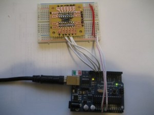
My setup is like this:

With LIS3LV02DL pin 3 connected to Arduino digital pin 11, LIS3LV02DL pin 2 connected to Arduino digital pin 12, pin 5 connected to digital pin 13 and pin 6 connected to digital pin 10.
The following is the code to retrieve data from the accelerometer using SPI.
#define DATAOUT 11//MOSI lis3lv02dl pin3
#define DATAIN  12//MISO lis3lv02dl pin2
#define SPICLOCK  13//sck lis3lv02dl pin5
#define CS 10//ss lis3lv02dl pin6, active low

//register addresses
const int REG_WHO_AM_I = 0x0f; //3A
const int REG_OFFSET_X = 0x16;
const int REG_OFFSET_Y = 0x17;
const int REG_OFFSET_Z = 0x18;
const int REG_GAIN_X = 0x19;
const int REG_GAIN_Y = 0x1A;
const int REG_GAIN_Z = 0x1B;
const int REG_CTRL_REG1 = 0x20;
const int REG_CTRL_REG2 = 0x21;
const int REG_CTRL_REG3 = 0x22;
const int REG_HP_FILTER_RESET = 0x23;
const int REG_STATUS_REG = 0x27;
const int REG_OUTX_L = 0x28;
const int REG_OUTX_H = 0x29;
const int REG_OUTY_L = 0x2a;
const int REG_OUTY_H = 0x2b;
const int REG_OUTZ_L = 0x2c;
const int REG_OUTZ_H = 0x2d;
const int REG_FF_WU_CFG = 0x30;
const int REG_FF_WU_SRC = 0x31;
const int REG_FF_WU_ACK = 0x32;
const int REG_FF_WU_THS_L = 0x34;
const int REG_FF_WU_THS_H = 0x35;
const int REG_FF_WU_DURATION = 0x36;
const int REG_DD_CFG = 0x38;
const int REG_DD_SRC = 0x39;
const int REG_DD_ACK = 0x3a;
const int REG_DD_THSI_L = 0x3c;
const int REG_DD_THSI_H = 0x3d;
const int REG_DD_THSE_L = 0x3e;
const int REG_DD_THSE_H = 0x3f;

//axis definitions
const int AXIS_X = 1;
const int AXIS_Y = 2;
const int AXIS_Z = 3;

const int CTRL_REG2_FS = 7;

void setup()
{
  byte b = 0;

  Serial.begin(9600);

  pinSetup();
  initSys();
  b = readRegister(REG_WHO_AM_I);
  Serial.println(b, HEX); //should be 3A

  setScale(1); //set range to 6g
}

void loop()
{
  Serial.print(" x = ");
  Serial.print(getValue(AXIS_X));
  Serial.print(" y = ");
  Serial.print(getValue(AXIS_Y));
  Serial.print(" z = ");
  Serial.println(getValue(AXIS_Z));
}

//transfer a byte using SPI
byte spiTransfer(volatile byte data)
{
  SPDR = data;

  while (!(SPSR & _BV(SPIF)));

  return SPDR;
}

void initSys()
{
  //disable device
  digitalWrite(CS,HIGH);

  //initialize SPI
  SPCR = _BV(SPE) | _BV(MSTR)| _BV(CPOL)| _BV(CPHA);

  //enable all axes
  writeRegister(REG_CTRL_REG1, 0x87);
}

void pinSetup()
{
  pinMode(DATAOUT, OUTPUT);
  pinMode(DATAIN, INPUT);
  pinMode(SPICLOCK,OUTPUT);
  pinMode(CS,OUTPUT);
}

byte getGain(int axis)
{
  byte r = 0;

  switch (axis)
  {
    case AXIS_X:
      r = readRegister(REG_GAIN_X);
    break;
    case AXIS_Y:
      r = readRegister(REG_GAIN_Y);
    break;
    case AXIS_Z:
      r = readRegister(REG_GAIN_Z);
    break;
    default:
      r = 0xff;
    break;
  }

  return r;
}

byte getOffset(int axis)
{
  byte r = 0;

  switch (axis)
  {
    case AXIS_X:
      r = readRegister(REG_OFFSET_X);
    break;
    case AXIS_Y:
      r = readRegister(REG_OFFSET_Y);
    break;
    case AXIS_Z:
      r = readRegister(REG_OFFSET_Z);
    break;
    default:
      r = 0xff;
    break;
  }

  return r;
}

void setScale(byte s)
{
  byte r = readRegister(REG_CTRL_REG2);

  if (s == 0) { // 2g
    r &= ~_BV(CTRL_REG2_FS);
  } else { //6g
    r |= _BV(CTRL_REG2_FS);
  }

 writeRegister(REG_CTRL_REG2, r);
}

int getValue(int axis)
{
  int r = 0;
  byte h, l;

  switch (axis)
  {
    case AXIS_X:
      l = readRegister(REG_OUTX_L);
      h = readRegister(REG_OUTX_H);
    break;
    case AXIS_Y:
      l = readRegister(REG_OUTY_L);
      h = readRegister(REG_OUTY_H);
    break;
    case AXIS_Z:
      l = readRegister(REG_OUTZ_L);
      h = readRegister(REG_OUTZ_H);
    break;
    default:
      l = 0;
      h = 0;
    break;
  }

  r = h << 8 | l;

  return r;
}

byte readRegister(byte reg)
{
   digitalWrite(CS, LOW);
   spiTransfer(reg | 0x80);
   byte b = spiTransfer(0);
   digitalWrite(CS, HIGH);

   return b;
}

void writeRegister(byte reg, byte data)
{
   digitalWrite(CS, LOW);
   spiTransfer(reg & 0x7F);
   spiTransfer(data);
   digitalWrite(CS, HIGH);
}
In the global constants area, I listed all the registers available to LIS3LV02DL. It is relatively straight-forward to use them and you can consult the product documentation for more information. The readRegister/writeRegister are the two main functions to read from and write to the registers defined earlier. getValue returns the accelerometer reading of the axis specified. setScale sets the scale to either 2G or 6G, etc.

