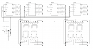
I was inspired by Paul’s 7 segment display and decided to build one myself. He used 4 common cathode 7 segment displays. In his original schematics, all the segments within a display shared one current limiting resistor which unfortunately affect the display brightness when different numbers of segments are lit. I happened to have two common anode dual 7 segment displays (QDSP-G545) so I decided to use them and four 74HC595 shift registers to build a four 7-seg display. Realizing that other people might be using either common anode or common cathode displays, I also built a library that can be used for either case.
Without further due, here’s the schematics of the 4 digit 7 segment display (click for higher resolution pictures):

For finer controls, I left the MR OE pins (pin 10 and 13) unconnected so that they can be controlled by program. But for general use, you can connect pin 10 (MR) to Vcc and pin 13 (OE) to ground so that the output is always enabled.
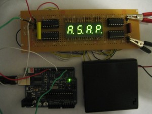
Here’s the finished display (the letters displayed are “A.S.A.P”)

It is fairly straight forward to write programs to interact with the above 4 digit display. The following C code offers a simple method disp() to display letters/digits that are predefined (see the comment section before the code and you will get an idea how to build your own symbols other than the ones included). The four boolean variables (dot1 to dot4) are used to turn on the decimal point on each segment independent of what is being displayed.
//aaaaaa
//f    b
//fggggb
//e    c
//eddddc p

//   abcdefgp ~abcdefgp DEC	~DEC
//1  00001100  11110011 12 	243
//2  11011010  00100101 218 101
//3  11110010  00001101 242 13
//4  01100110  10011001 102	153
//5  10110110  01001001 182	73
//6  10111110  01000001 190	65
//7  11100000  00011111 224	31
//8  11111110  00000001 254	1
//9  11110110  00001001 246	9
//0  11111101  00000010 253	2
//A  11101110  00010001 238	17
//b  00111110  11000001 62	193
//c  00011010  11100101 26	229
//C  10011100  01100011 156	99
//d  01111010  10000101 122 133
//e  11011110  00100001 222 33
//E  10011110  01100001 158 97
//F  10001110  01110001 142	113
//g  11110110  00001001 246	9
//H  01101110  10010001 110	145
//h  00101110  11010001 46	209
//I  01100000  10011111 96 	159
//J  01111000  10000111 120	135
//L  00011100  11100011 28 	227
//n  00101010  11010101 42	213
//o  00111010  11000101 58	197
//P  11001110  00110001 206	49
//q  11100110  00011001 230	25
//r  00001010  11110101 10	245
//S  10110110  01001001 182 73
//t  00011110  11100001 30	225
//u  00111000  11000111 56	199
//U  01111100  10000011 124	131
//y  01110110  10001001 118	137
//-  00000010  11111101 2 	253
//-  10000000  01111111 128	127
//-  00010000  11101111 16	239
//.  00000001  11111110 1 	254
//|| 01101100  10010011 108	147
//=  10010000  01101111 144 111
//=  10000010  01111101 130 125
//=  00010010  11101101 18	237
//=- 10010010  01101101 146 109

int latchPin = 10;
int clockPin = 7;
int dataPin = 3;

//note that for common cathode displays the
//bit values are inverted (see code)
const int COMMON_ANODE = 1; //1 CA, 0 CC

struct CharMap
{
  char c;
  byte v;
};

const int cmap_len = 41;
struct CharMap cmap[] = {
{' ', 0},
{'1', 12},
{'2', 218},
{'3', 242},
{'4', 102},
{'5', 182},
{'6', 190},
{'7', 224},
{'8', 254},
{'9', 246},
{'0', 253},
{'A', 238},
{'b', 62},
{'c', 26},
{'C', 156},
{'d', 122},
{'e', 222},
{'E', 158},
{'F', 142},
{'g', 246},
{'H', 110},
{'h', 46},
{'I', 96},
{'J', 120},
{'L', 28},
{'n', 42},
{'o', 58},
{'P', 206},
{'q', 230},
{'r', 10},
{'S', 182},
{'t', 30},
{'u', 56},
{'U', 124},
{'y', 118},
{'-', 2},
{'~', 128},
{'_', 16},
{'.', 1},
{'|', 108},
{'=', 144}
};

byte getCode(char c)
{
  byte r = 2;

  for (int i = 0 ; i < cmap_len ; i++) {
    if (c == cmap[i].c) {
      r = cmap[i].v;
      break;
    }
  }

  return r;
}

//display c1 c2 c3 c4
//Note the boolean values for dot1 dot2 dot3 and dot4
//indicates whether or not to show the decimal point
void disp(char c1, bool dot1, char c2, bool dot2, char c3, bool dot3, char c4, bool dot4)
{
  byte b1 = getCode(c1);
  byte b2 = getCode(c2);
  byte b3 = getCode(c3);
  byte b4 = getCode(c4);

  if (dot1 == true) b1 += 1;
  if (dot2 == true) b2 += 1;
  if (dot3 == true) b3 += 1;
  if (dot4 == true) b4 += 1;

  if (COMMON_ANODE == 1) {
    b1 = 255 - b1;
    b2 = 255 - b2;
    b3 = 255 - b3;
    b4 = 255 - b4;
  }

  digitalWrite(latchPin, LOW);

  shiftOut(dataPin, clockPin,  b4);
  shiftOut(dataPin, clockPin,  b3);
  shiftOut(dataPin, clockPin,  b2);
  shiftOut(dataPin, clockPin,  b1);

  digitalWrite(latchPin, HIGH);
}

void setup7seg()
{
  pinMode(latchPin, OUTPUT);
  pinMode(clockPin, OUTPUT);
  pinMode(dataPin, OUTPUT);

  disp(' ', false, ' ', false, ' ', false, ' ', false);
}

void shiftOut(uint8_t dataPin, uint8_t clockPin, byte val)
{
	int i;

	for (i = 0; i < 8; i++)  {
		digitalWrite(dataPin, (val & _BV(i)));
                delayMicroseconds(10);
		digitalWrite(clockPin, HIGH);
                delayMicroseconds(10);
		digitalWrite(clockPin, LOW);
                delayMicroseconds(10);
	}
}

void setup()
{
  setup7seg();
}

void loop()
{
  disp('d',false,'I',false,'S',false,'C',false); //displays the word dISC
  delay(1000);
}
The shiftOut method is actually included in standard Arduino libraries, the reason I included it in my code is that I had to add slight delay between each digitalWrite otherwise the output is not always correct. I suspect this is due to the long wiring I used on the circuit board.
See also: An 8-Digit 7 Segment Display

