H-bridge is frequently used to control DC motors and stepper motors. When controlling a bipolar stepper motor, two full H-bridges are needed. There are many H-bridge ICs (like L298, MPC17529 and SN754410 which is a quad half H-bridge) for just that purpose. But if you are on a budget, you may want to consider building a dual H-bridge yourself.
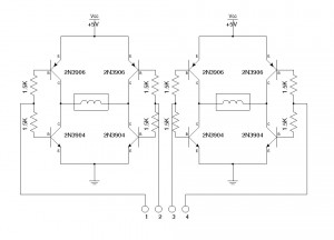
The following schematic shows a simple dual H-bridge using eight general purpose transistors (2N3904 and 2N3906). Given the maximum Iceo of roughly 200mA, this circuit can be used to drive a small bipolar stepper motor operating between 5V and 12V, such as the stepper motors found in most floppy drives and CD/DVD drives.

The four control inputs (1,2,3,4) can be driven with Arduino‘s digital pins (i.e. 2,3,4,5) directly. The following program illustrates how to signal the four leads of a bipolar stepper motor for it to rotate. Of course, there’s already a stepper motor library built for this purpose. The program below is helpful when learning the sequence of the pulses required by bipolar stepper motors.
int coila1 = 2;
int coila2 = 3;
int coilb1 = 4;
int coilb2 = 5;

void setup()
{
  pinMode(coila1, OUTPUT);
  pinMode(coila2, OUTPUT);
  pinMode(coilb1, OUTPUT);
  pinMode(coilb2, OUTPUT);
}

void loop()
{
  digitalWrite(coila1, HIGH);
  digitalWrite(coila2, LOW);
  digitalWrite(coilb1, LOW);
  digitalWrite(coilb2, LOW);
  delay(10);

  digitalWrite(coila1, LOW);
  digitalWrite(coila2, LOW);
  digitalWrite(coilb1, HIGH);
  digitalWrite(coilb2, LOW);
  delay(01);

  digitalWrite(coila1, LOW);
  digitalWrite(coila2, HIGH);
  digitalWrite(coilb1, LOW);
  digitalWrite(coilb2, LOW);
  delay(10);

  digitalWrite(coila1, LOW);
  digitalWrite(coila2, LOW);
  digitalWrite(coilb1, LOW);
  digitalWrite(coilb2, HIGH);
  delay(10);
}
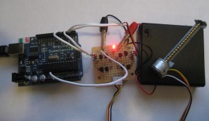
Here is a picture of an Arduino controlled CD-ROM stepper motor (the one controlling the tray mechanism) powered by the above dual H-bridge (with an added LED for power).

Update
The PNP transistors in the original schematics had C and E swapped. This has been corrected with the latest schematics update.

