After going through some of the tutorials on Arduino’s site, I really started to appreciate what a powerful platform Arduino really is. A lot of seemingly complex software/hardware interactions can be made quite easy with relatively few components and little coding. As one of my first Arduino based projects, I built a simple power inverter driven by Arduino.
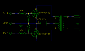
The following is the circuit diagram of this inverter. As you can see, the two MOSFETs attached to the center-tapped transformer (mine was removed from an old UPS), when driven by a rectangular or sinusoidal wave, will produce alternating current in the primary winding. The pull-down resistors (1M) are necessary to prevent any electrical noise. The 10K resistors are not strictly necessary, but I placed them there to prevent damage to the Arduino board in case of a MOSFET failure.

The gates of the two MOSFETS are connected to two digital pins of the Arduino board. The following code shows how to use the simple bit-banging technique to generate the 60Hz square wave needed for the inverter.
int pin1 =  4;
int pin2 =  5;

void setup()   {
  pinMode(pin1, OUTPUT);
  pinMode(pin2, OUTPUT);
}

void loop()
{
  digitalWrite(pin1, HIGH);
  digitalWrite(pin2, LOW);
  delay(7);
  digitalWrite(pin1, LOW);
  digitalWrite(pin2, HIGH);
  delay(7);
}
The benefit of using an Arduino to control the waveform generation is that the output frequency can be precisely controlled. Of course, if the output waveform accuracy is a concern, more advanced PWM signal with a 50% duty cycle should be used to drive the MOSFETs. An inverter gate would be necessary in this case to obtain the opposite phase pulse signal to drive the second MOSFET. We can even use Arduino to generate pure sinusoidal wave to drive this inverter.
In my example above, the gate-to-source voltage comes directly from the TTL output of the Arduino digital pin. This voltage is acceptable for a 12V Vcc. If the circuit requires higher DC voltage, the gate-to source-voltage may need to be amplified for the MOSFETS to switch properly. The optimal driven voltage can be found on the datasheet of the particular MOSFET used. In this case, it is RFP50N06.

