Hall effect sensors can be found in many common household gadgets. Most brushless DC motors for instance, like those used in computer cooling fans, contain Hall effect sensors in the driving circuits. I recently replaced one of the cooling fans in my computer and decided to do some experiments with the Hall effect sensor in that old fan.
After removing the fan rotor you can see the stator and the control circuits. This particular fan is driven by a single chip ATS 277(the data sheet can be found here), which is a complementary output Hall effect latch. It turns on and off the alternate side of the poles depending on the rotor’s position.
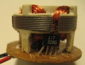
So, using this Hall effect latch IC, we can build a simply electronic circuit that can be used to detect the polarity of a magnet (the magnetic field has to be strong enough to trigger the sensor due to its limited sensitivity).
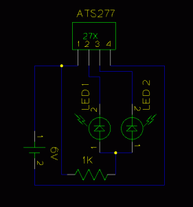
Here is the schematics I used to build such a detector:
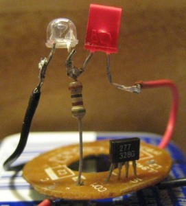
and here is a picture of the detector after it was built.
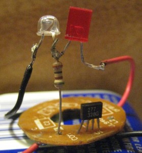
When the circuit is powered on, one of the two output will be latched at low and thus the LED connected to that pin will light up:
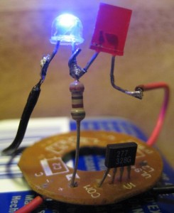
If the Hall sensor detects a strong enough magnetic field, the original pin with the low output will turn high and the other pin will turn low. Thus the blue LED will be off and the red LED will be turned on (see the picture below, note that the red LED is illuminated albeit it is a little dark compared to the blue one).
By alternating the polarity of the magnetic field (e.g. use the opposite side of the magnet), the LEDs will alternate between blue and red, depending on the polarity used.

